Encapsulating Actin Cytoskeletons in Giant Unilamellar Vesicles: A Guide for Synthetic Cell Research
This article provides a comprehensive resource for researchers and professionals on the encapsulation of actin networks in Giant Unilamellar Vesicles (GUVs), a cornerstone of bottom-up synthetic biology.
Encapsulating Actin Cytoskeletons in Giant Unilamellar Vesicles: A Guide for Synthetic Cell Research
Abstract
This article provides a comprehensive resource for researchers and professionals on the encapsulation of actin networks in Giant Unilamellar Vesicles (GUVs), a cornerstone of bottom-up synthetic biology. We explore the foundational role of the actin cytoskeleton as the cell's primary mechanical machinery and detail the most effective production methods, including inverted emulsion and cDICE, for achieving high encapsulation efficiency. The scope extends to troubleshooting common experimental challenges, validating the resulting synthetic cell constructs through advanced image analysis and functional assays, and comparing the performance of different methodological approaches. This guide synthesizes current best practices to advance the construction of biomimetic artificial cells for fundamental research and therapeutic applications.
The Actin Cytoskeleton and GUVs: Building a Mechanical Framework for Synthetic Cells
Why GUVs are an Ideal Biomimetic System for Cytoskeletal Studies
Giant Unilamellar Vesicles (GUVs) are micrometer-sized, closed freestanding lipid bilayers that faithfully mimic the size, curvature, and basic structure of the plasma membrane of eukaryotic cells [1] [2]. Their cell-like dimensions (typically 1-100 μm) and ease of visualization under optical microscopy have established them as one of the most powerful biomimetic membrane model systems available [1] [2]. In the study of biological processes, simplified models play a crucial role by allowing researchers to analyze complex systems in a controlled environment, much like how maps serve as simplified representations of the Earth [1]. GUVs fulfill this role exceptionally well for membrane and cytoskeletal studies because they enable the reproduction of simplified cell models in the laboratory, making it possible to investigate how membranes and associated structures respond to various stimuli without the complexity of entire biological systems [1].
The principal advantage of GUVs for cytoskeletal research derives from their micron scale, which enables ease of visualization and manipulation using microscopy and microhandling techniques [3]. This unique combination of properties makes GUVs an ideal tool for bottom-up synthetic biology approaches, where purified components are assembled to recreate minimal functional cellular units [4] [5]. Specifically for cytoskeletal studies, GUVs provide a confined reaction space that mimics the physical constraints inside living cells, allowing researchers to investigate how cytoskeletal assemblies form structures that span the entirety of the cell, with their shape naturally determined by cell-sized confinement [4].
Advantages of GUVs for Cytoskeletal Research
Key Benefits for Cytoskeleton-Membrane Interaction Studies
GUVs offer several distinct advantages that make them particularly suitable for studying cytoskeletal networks and their interactions with membranes. First, the ability to precisely control the membrane's molecular composition is fundamental for systematic studies [1]. This composition can range from single lipid species to complex mixtures of several lipids, including natural lipid extracts [1]. Furthermore, GUVs can be functionalized with specific membrane-bound proteins or biotinylated lipids that enable precise attachment of actin filaments or nucleation factors [5].
A second major advantage is the ability to encapsulate cytoskeletal proteins inside the GUVs, creating a cell-like environment where network assembly can occur under controlled confinement [4]. This encapsulation better mimics confinement conditions inside living cells as opposed to conventional biochemical reconstitution [4]. The confinement itself affects actin morphology and organization, which can be systematically studied using GUVs [5].
Third, GUVs serve as a deformable substrate whose mechanical properties can be precisely quantified and related to cytoskeletal activity. Researchers can observe how actin networks generate forces that deform membranes and how these interactions affect overall vesicle shape and mechanics [5] [6]. This has proven essential for understanding physical mechanisms behind cellular processes such as motility, division, and filopodia formation [5].
Table 1: Key Advantages of GUVs for Cytoskeletal Studies
| Feature | Research Benefit | Application Examples |
|---|---|---|
| Cell-like Size | Enables study of cytoskeletal organization under physiological confinement | Actin cortex formation [5]; microtubule network organization [6] |
| Controlled Composition | Systematic analysis of lipid-protein interactions | Membrane attachment via PIP2/N-WASP [5]; lipid raft domains [7] |
| Direct Visualization | Real-time observation of dynamic processes | Actin polymerization dynamics [4]; shape fluctuations [6] |
| Membrane Deformability | Investigation of force generation and mechanical coupling | Actin-driven protrusions [5]; vesicle shape changes [8] [6] |
| Encapsulation Capacity | Study of network assembly in confined space | Minimal cytoskeleton reconstitution [7] [4] [5] |
Comparison of GUV Production Methods for Cytoskeletal Studies
Different methods for GUV production offer varied advantages and limitations, making them differentially suitable for cytoskeletal encapsulation studies. The selection of an appropriate preparation technique is critical to fine-tuning the properties of GUVs and ensuring they are suitable for specific applications [1].
Table 2: Comparison of GUV Production Methods for Cytoskeletal Encapsulation
| Method | Encapsulation Efficiency | Cytoskeletal Compatibility | Key Advantages | Major Limitations |
|---|---|---|---|---|
| Electroformation [1] | Low | Limited to specific buffers and low ionic strength | Simple equipment; high quality vesicles | Restricted lipid compositions; low salt buffers |
| Gel-Assisted Hydration [1] [2] | Moderate | Compatible with physiological buffers | Works with high ionic strength; simple setup | Polymer contamination possible [2] |
| Emulsion Transfer Methods (cDICE) [4] [9] | High | Excellent for proteins and physiological conditions | High encapsulation efficiency; rapid production | Complex setup; potential oil contamination |
| Microfluidic Methods [10] | High | Good for controlled encapsulation | Size control; high throughput | Technical complexity; device fabrication |
For cytoskeletal studies specifically, emulsion-based methods like continuous droplet interface crossing encapsulation (cDICE) have proven particularly valuable because they allow efficient encapsulation of complex protein systems inside GUVs [4]. This method simplifies the overall procedure of encapsulation within GUVs and speeds up the process, allowing researchers to confine and observe the dynamic evolution of network assembly inside lipid bilayer vesicles [4]. The protocol takes about 15-20 minutes from start to GUV collection and imaging, which is crucial for maintaining the activity of cytoskeletal proteins [4].
Experimental Protocols for Cytoskeletal Reconstitution in GUVs
cDICE Method for Actin Encapsulation
The cDICE technique has emerged as a powerful method for reconstituting cytoskeletal networks inside GUVs due to its high encapsulation efficiency and compatibility with physiological conditions [4]. Below is a detailed protocol for encapsulating actin and actin-binding proteins using this method:
Preparation of Oil-Lipid Mixture (Perform in fume hood):
- Take 0.5 mL of chloroform in a 15 mL glass vial. Add 88 μL of 25 mg/mL DOPC, 9.3 μL of 50 mg/mL cholesterol, and 5 μL of 1 mg/mL dioleoyl-phosphoethanolamine-lissamine rhodamine B (rhodamine PE) [4].
- Pipette 7.2 mL of silicone oil and 1.8 mL of mineral oil in a second 15 mL vial [4].
- Mix the oils by vortexing at maximum rotational speed (3200 RPM) for 10 seconds, then add to the vial containing the lipid-chloroform mixture and vortex immediately for 10-15 seconds at maximum speed [4].
- Sonicate the lipid-in-oil dispersion in a bath sonicator (80 W, 40 kHz) at room temperature for 30 minutes. Use immediately or store at 4°C for maximum 24 hours [4].
Protein Solution Preparation:
- Prepare 1-10 μM of actin in globular actin buffer (G-buffer: 5 mM Tris-HCl, pH 8.0, and 0.2 mM CaCl₂), including 10% fluorescently labeled actin (e.g., ATTO 488 actin) for visualization [4].
- Add filamentous actin polymerization buffer (F-buffer: 50 mM KCl, 2 mM MgCl₂, and 3 mM ATP in 100 mM Tris, pH 7.5) to initiate actin polymerization on ice [4].
- Wait for 15 minutes to allow for initiation of actin polymerization on ice before adding crosslinkers (e.g., fascin, α-actinin) at the desired molar ratio [4].
- Prepare actin-binding proteins (ABPs) separately in microtubes [4].
Vesicle Generation:
- Mount a 3D-printed shaft on a benchtop stir plate and set rotational speed to 1200 RPM [4].
- Mount a 3D-printed cDICE chamber on the shaft [4].
- Add the lipid-in-oil mixture and protein solutions to the rotating chamber following specific timing protocols to ensure proper encapsulation [4].
- Collect GUVs after formation for immediate imaging or further experimentation [4].
Diagram 1: cDICE workflow for cytoskeletal encapsulation.
Phase-Separated GUVs for Membrane Domain Studies
A more advanced application involves creating phase-separated GUVs containing liquid-disordered (Ld) and liquid-ordered (Lo) domains to better mimic the lipid raft heterogeneity of cellular membranes [7]. The following protocol enables simplified one-pot production of such systems:
Emulsion Transfer Protocol for Phase-Separated GUVs:
- Generate a lipid-monolayer by emulsifying a protein solution in a lipid/oil mixture, selecting lipids of varying phase transition temperatures to yield phase separation in the resultant GUVs [7].
- Gently transfer this emulsion on top of a lipid-in-oil solution in another tube, resulting in the formation of a water-oil interface [7].
- Centrifuge at elevated temperatures (ideally at 37°C to retain protein activity) [7].
- Collect GUVs for imaging and analysis of cytoskeletal organization relative to membrane domains [7].
This method simplifies the in vitro reconstitution of cytoskeletal proteins within phase-separated GUVs without using a cumbersome laboratory setup, serving as a convenient method for studying the mechanics of cytoskeletal-membrane interactions in confinement [7].
Research Applications and Case Studies
Reconstitution of Actin Networks
GUV-based systems have enabled detailed studies of various actin structures and their effects on membrane properties. Researchers have successfully reconstituted multiple actin architectures inside GUVs by varying the composition of actin-binding proteins:
Branched Networks: Using nucleation-promoting factors like N-WASP and the Arp2/3 complex, researchers have created branched actin networks similar to those found in lamellipodia [5]. When specifically targeted to the membrane through PIP2 lipids or other attachment strategies, these networks can generate protrusive forces that deform GUV membranes, creating filopodia-like extensions [5]. One study demonstrated that such membrane-coupled actin assembly leads to both inward and outward protrusions emerging from dendritic networks, with the exact deformation pattern dependent on the concentration of capping proteins [5].
Bundled Actin Structures: The addition of crosslinking proteins like fascin and α-actinin to encapsulated actin results in the formation of bundled actin structures [5]. These bundles can organize into ring-like structures near the membrane or form protrusions extending from the GUV surface [5]. Interestingly, the competition between different actin-binding proteins significantly affects network morphology, as demonstrated by Wubshet et al., who showed that fascin and Arp2/3 compete for G-actin, with protrusions forming only in the presence of sufficient fascin concentrations [5].
Actin-Myosin Contractile Systems: The encapsulation of both actin and myosin II motors enables the reconstitution of contractile networks that mimic the actomyosin cortex of cells [5]. These systems can generate tension and lead to dramatic shape changes in GUVs. Studies have shown that the balance between membrane attachment and contractile forces determines whether the cortex remains membrane-associated or detaches, creating cortical discontinuities similar to those observed in certain cellular processes [5].
Microtubule-Motor Systems in GUVs
Beyond actin systems, GUVs have proven valuable for studying microtubule networks and their interactions with membranes. Recent work has encapsulated active microtubule networks driven by kinesin molecular motors inside GUVs [6]. This minimal synthetic cell model demonstrates how cytoskeletal forces acting on a biomimetic membrane affect its deformations:
Active Fluctuation Analysis: When encapsulated inside GUVs, active microtubule networks organize into a three-dimensional network of extensile bundles that continuously exert forces on the membrane [6]. Quantitative analysis reveals fluctuation spectra that differ in both spatial and temporal decays from their counterparts in thermal equilibrium [6]. These active deformations are roughly one order of magnitude greater than passive fluctuations at all mode numbers, following a 〈∣u_q∣^2〉 ≈ q^−3 decay that indicates bending-dominated deformations [6].
Correlated Activity: The membrane dynamics in these systems are governed by correlated activity of the encapsulated cytoskeletal components rather than thermal fluctuations alone [6]. Using simulations, researchers have extended the classical framework of membrane fluctuations to active cytoskeleton-driven vesicles, demonstrating how activity governs membrane dynamics and the roles of confinement, membrane material properties, and cytoskeletal forces [6].
Diagram 2: Cytoskeleton-membrane interactions in GUVs.
Mechanical Stabilization by Actin Networks
Membrane-localized actin filaments have been shown to stabilize GUVs against external deforming forces [8]. This stabilization function mimics the protective role of the cortical actin network in cells, demonstrating how GUVs can be used to study both active deformation processes and mechanical reinforcement provided by cytoskeletal elements.
The Scientist's Toolkit: Essential Research Reagents
Table 3: Essential Research Reagents for GUV Cytoskeletal Studies
| Reagent Category | Specific Examples | Function in Experiments | Commercial Sources |
|---|---|---|---|
| Lipids | DOPC, Cholesterol, Rhodamine PE | Membrane formation, fluidity control, visualization | Avanti Polar Lipids [4] |
| Cytoskeletal Proteins | Actin (skeletal muscle), ATTO 488-actin | Primary filament formation, visualization | Cytoskeleton Inc., Hypermol [4] |
| Actin-Binding Proteins | Fascin, α-actinin, Arp2/3 complex | Crosslinking, nucleation, network regulation | Homemade, commercial sources [4] [5] |
| Molecular Motors | Myosin II, kinesin tetramers | Force generation, network contraction | Commercial sources [5] [6] |
| Buffers & Reagents | G-buffer, F-buffer, ATP, MgCl₂ | Polymerization control, energy source | Sigma-Aldrich, Fisher Scientific [4] |
| Equipment | 3D-printed cDICE chamber, sonicator, vortex | Vesicle production, sample preparation | Formlabs, Fisher Scientific [4] |
Giant Unilamellar Vesicles represent an ideal biomimetic system for cytoskeletal studies due to their unique combination of cell-like size, compositional control, and experimental accessibility. The development of advanced encapsulation techniques like cDICE has enabled researchers to reconstitute increasingly complex cytoskeletal networks inside GUVs, from simple actin filaments to active systems containing multiple cytoskeletal proteins and molecular motors. These minimal systems have provided fundamental insights into the physical mechanisms underlying cytoskeleton-driven membrane deformations, network organization under confinement, and the mechanical stabilization provided by cortical structures.
As GUV technology continues to advance, with improved production methods and more sophisticated biochemical reconstitution capabilities, these biomimetic systems will undoubtedly play an increasingly important role in deciphering the complex interplay between cytoskeletal networks and cellular membranes. The quantitative approaches enabled by GUV-based systems, including flicker spectroscopy, force measurements, and dynamic imaging, provide a solid foundation for building physical models of cell shape changes that bridge the gap between in vitro reconstitution and cellular physiology.
The Role of Actin as the Cell's Principal Mechanical Machinery
The actin cytoskeleton serves as the primary mechanical machinery within eukaryotic cells, generating and withstanding physical forces essential for processes including cell migration, cytokinesis, and morphogenesis [11] [12]. This dynamic polymer network converts chemical energy into mechanical work through its interaction with motor proteins and cross-linking factors, allowing cells to adapt their shape, generate traction, and respond to environmental physical cues [13]. In physiological three-dimensional environments, actin organizes into structures distinct from those observed on two-dimensional substrates, underscoring the importance of studying its mechanics in contextually relevant systems such as giant unilamellar vesicles (GUVs) [14] [15]. These minimal cell models provide a controlled platform for dissecting how actin architecture dictates mechanical output, a relationship crucial for understanding cell behavior in development, homeostasis, and disease.
Actin Architecture and Force Generation Mechanisms
Structural Organization of Actin Networks
Actin networks assemble into diverse architectures defined by specific actin-binding proteins. The Arp2/3 complex nucleates branched actin networks that produce protrusive forces, while formins processively assemble unbranched actin bundles such as filopodia and stress fibers [15]. Fascin constructs tightly packed, parallel actin bundles that provide rigid structural support for filopodia and other cellular protrusions [16]. These structural variations directly determine the mechanical properties and force-generation capabilities of the cytoskeleton. In GUV-based studies, these distinct architectures demonstrate unique reorganization behaviors when subjected to external forces, with fascin-bundled networks collapsing and aligning along aspiration axes while branched networks resist deformation and maintain structural integrity [14].
Molecular Mechanisms of Contractility
Cellular contractility primarily emerges from the interaction between filamentous actin (F-actin) and myosin II motor proteins [11] [12]. Myosin II molecules self-assemble into bipolar filaments that walk toward the barbed ends of adjacent actin filaments, generating shear forces that pull anti-parallel filaments past one another [12]. In disordered actomyosin networks, compressive forces buckle actin filaments, leaving net tension that drives contraction [11]. Computational models reveal that myosin filament structure—including the number of motor heads, bare zone length, and spatial distribution—profoundly influences both the magnitude and efficiency of force generation [11] [12]. This contractile apparatus enables cells to generate, transmit, and sense mechanical forces with high spatial and temporal precision.
Application Notes: GUVs for Actin Mechanics Research
GUVs as Minimal Cellular Models
Giant unilamellar vesicles provide an ideal reconstitution platform for investigating actin mechanics in a controlled, cell-like environment. When encapsulated within GUVs, actin networks interact with the lipid membrane, enabling researchers to study force transmission and shape changes in a minimal system [14] [17]. Studies demonstrate that polymerized actin significantly increases membrane rigidity, with F-actin accumulating near the membrane and enhancing resistance to deformation [17]. The encapsulation of active cytoskeletal components, including molecular motors and cross-linkers, produces dramatic shape fluctuations and traveling membrane deformations reminiscent of living cells [6]. These reconstituted systems enable precise manipulation of biochemical and physical parameters that is impossible in living cells, making GUVs invaluable for mechanistic studies.
Technical Considerations for Actin Encapsulation
Successful actin encapsulation requires careful optimization of lipid composition, buffer conditions, and polymerization triggers. Phase-separated GUVs with liquid-ordered and liquid-disordered domains better mimic cellular membrane complexity and can be produced using emulsion transfer methods that preserve protein activity [18]. Actin polymerization inside GUVs typically requires MgCl₂ and ion carriers to facilitate Mg²⁺ transport across the membrane [17]. Maintaining physiological temperatures during GUV production is crucial for retaining cytoskeletal protein function, while including crowding agents like Ficoll70 mimics intracellular conditions that promote proper network assembly [18]. These technical considerations ensure the reconstitution of physiologically relevant actin architectures and dynamics.
Table 1: Key Experimental Findings from Actin-GUV Studies
| Experimental System | Key Finding | Mechanical Implication | Citation |
|---|---|---|---|
| Fascin-bundled actin in GUVs under aspiration | Bundles collapse and align along aspiration axis | Network architecture determines deformation response | [14] |
| F-actin encapsulated in DMPC GUVs | Polymerized actin increases membrane rigidity | Actin networks resist deformation | [17] |
| Active MT/kinesin/anillin networks in GUVs | Correlated activity drives membrane fluctuations | Active forces dictate temporal scaling of deformations | [6] |
| Branched actin networks in GUVs under aspiration | Networks resist entry into micropipette | Interconnected architecture provides structural stability | [14] |
Detailed Experimental Protocols
Protocol 1: Encapsulation of Actin Networks in Phase-Separated GUVs
This protocol describes the production of phase-separated GUVs containing reconstituted actin networks using an emulsion transfer method, adapted from established techniques [18].
Lipid Mixture Preparation
- Prepare lipid stock solutions in chloroform: DOPC (25 g/L), DOPG (25 g/L), DPPC (25 g/L), DPPG (10 g/L), and Cholesterol (18 g/L)
- Combine in molar ratio DOPC:DOPG:DPPC:DPPG:Chol:Biotinyl CAP PE (17.499:7.5:30.5:13.5:30:1)
- Add 0.001 mol% Atto655-DOPE fluorescent dye for membrane visualization
- Evaporate chloroform under nitrogen gas flow and desiccate for 30 minutes to remove residual solvent
- Resuspend dried lipid film in decane (20 μL) and mineral oil (500 μL) to final concentration of 3.2 mM
- Sonicate lipid-in-oil mixture at 50°C for 30 minutes, then incubate at 37°C before use
Actin Bundle Encapsulation Mixture
- Prepare actin master mix (A-Mix) containing 86% G-actin, 10% Atto488-actin, and 4% biotinylated actin in water
- For final concentration of 35.42 μM A-Mix, combine 6.39 μL of 2 g/L G-actin, 1.48 μL of 1 g/L Atto488-actin, 1.19 μL of 0.5 g/L biotinylated actin, and 0.9 μL H₂O
- Maintain on ice and protect from light until encapsulation
- Add fascin at 1:5 molar ratio to actin to induce bundle formation [14]
GUV Formation via Emulsion Transfer
- Emulsify inner actin solution in lipid/oil mixture by pipetting to create volumetric confinement before full network assembly
- Transfer emulsion to rotating cDICE chamber containing outer aqueous solution (∼200 mOsm) and oil/lipid mixture
- Include 7.5% Optiprep in inner solution to facilitate GUV sedimentation via density gradient
- Centrifuge at elevated temperature (37°C) to maintain protein activity while achieving phase separation
- Collect GUVs for imaging and analysis
GUV Encapsulation Workflow: Diagram outlining the key steps for encapsulating actin networks in phase-separated giant unilamellar vesicles.
Protocol 2: Micropipette Aspiration of Actin-GUVs
This protocol details the application of micropipette aspiration to assess mechanical responses of encapsulated actin networks, building on established methods [14].
Micropipette Preparation
- Pull standard glass capillaries using a Sutter P-87 pipette puller to create parallel-walled tips
- Manually cut pipettes to diameters of 4-8 μm using a heated glass rod
- Submerge pipettes in 1% BSA solution to prevent GUV adhesion
- Mount pipette in holder and connect to fluidic system with filling syringe and pressure transducer
- Eliminate all air bubbles from the system
- Maintain slight positive pressure until GUV is positioned for aspiration
Aspiration and Imaging
- Position GUV (diameter 15-40 μm) adjacent to micropipette using micromanipulator
- Apply negative pressure using pressure transducer to initiate aspiration
- Acquire timelapse images every 300 ms using spinning disk confocal microscopy
- Simultaneously capture fluorescence images of actin networks and brightfield images of pipette tip
- Analyze network reorganization using ImageJ and Python's matplotlib library
Data Analysis
- Extract GUV contour R(φ, t) from equatorial plane images
- Compute membrane deformations ΔR = R - R₀, where R₀ is mean radius
- Decompose contour into Fourier modes to quantify deformation magnitudes
- Perform statistical analysis on intensity profiles pre- and post-aspiration
- Compare deformation spectra between different actin architectures
Mechanical Testing Workflow: Steps for micropipette aspiration of actin-encapsulating GUVs to assess mechanical properties.
Research Reagent Solutions
Table 2: Essential Reagents for Actin-GUV Research
| Reagent | Function | Example Application | Technical Notes |
|---|---|---|---|
| DOPC/DPPC/Cholesterol lipids | Membrane formation with phase separation | Creating domain-forming GUVs | 70:30 DOPC:Cholesterol ratio common [14] |
| Fascin | Actin bundling protein | Forming parallel actin bundles | 1:5 fascin:actin ratio for bundles [14] |
| Arp2/3 complex with VCA | Nucleates branched actin networks | Creating dendritic architectures | 500 nM Arp2/3 + 500 nM His₆-tag VCA [14] |
| ATTO488-actin | Fluorescent actin labeling | Network visualization | 10% of total actin for imaging [18] |
| Biotinylated actin | Membrane attachment points | Linking cortex to membrane | 4% of total actin concentration [18] |
| Optiprep | Density gradient medium | GUV sedimentation | 7.5% in inner solution [14] |
| MgCl₂ with A23187 ion carrier | Actin polymerization trigger | Inducing F-actin assembly in GUVs | Enables Mg²⁺ transport across membrane [17] |
Data Analysis and Interpretation
Quantitative Analysis of Membrane Deformations
The mechanical behavior of actin-encapsulating GUVs can be quantified through flicker spectroscopy, which analyzes membrane fluctuations by decomposing the GUV contour into Fourier modes [6]. The contour R(φ, t) is described as:
$$R(\phi ,t)={R}{0}\left(1+\sum _{q}^{{q}{\max }}{u}_{q}(t){{\rm{e}}}^{{\rm{i}}q\phi }\right)$$
where uq represents the magnitude of deformations at mode number q. For passive vesicles, the power spectrum follows:
$$\left\langle | {u}{q}{| }^{2}\right\rangle \approx \frac{{k}{{\rm{B}}}T}{\kappa }\frac{1}{{q}^{3}+\bar{\sigma }q}$$
where κ is bending rigidity and $\bar{\sigma }=\sigma {R}_{0}^{2}/\kappa$ is normalized tension [6]. Active GUVs exhibit fluctuation spectra approximately one order of magnitude higher than passive vesicles across all mode numbers, indicating that active forces dominate over thermal excitations [6].
Architectural Determinants of Mechanical Response
Actin network architecture profoundly influences mechanical behavior under load. Fascin-bundled networks undergo dramatic reorganization when aspirated, collapsing and aligning parallel to the flow axis [14]. In contrast, Arp2/3-nucleated branched networks resist aspiration, maintaining structural integrity outside the pipette while only the membrane is drawn in [14]. These differential responses emerge from structural properties: fascin bundles form rigid elements that can reorient as units, while branched networks distribute forces through interconnected filaments. Computational models further reveal that myosin II filament structure—including head number and bare zone length—significantly impacts contractile force generation in both bundled and networked architectures [11] [12].
Table 3: Actin Network Properties and Mechanical Responses
| Actin Architecture | Structural Features | Response to Aspiration | Force Generation Characteristics |
|---|---|---|---|
| Fascin-bundled | Parallel filaments, hexagonal packing | Collapse and alignment along flow axis | High rigidity, coordinated contraction |
| Arp2/3-branched | Dendritic network, 70° branches | Resistance to entry, structural maintenance | Distributed stress, isotropic resistance |
| Myosin-activated | Bipolar filaments, cross-linked | Contraction and tension development | Tunable by myosin filament structure |
GUV-encapsulated actin networks provide a powerful reductionist system for elucidating how cytoskeletal architecture dictates cellular mechanical output. The protocols and analyses presented here enable researchers to reconstitute specific actin structures, apply controlled mechanical stimuli, and quantitatively measure material responses. These approaches reveal fundamental design principles whereby structural plasticity of actin-binding proteins like fascin enables adaptation to varied mechanical demands [16], and how motor filament properties tune contractile force generation [11] [12]. For drug development professionals, these minimal systems offer platforms for screening compounds targeting cytoskeletal mechanics with relevance to cancer metastasis, developmental disorders, and degenerative diseases. The continuing refinement of GUV-based actin models promises deeper insights into how cells harness this versatile mechanical machinery to shape form, generate force, and respond to their physical environment.
The reconstitution of actin networks inside giant unilamellar vesicles (GUVs) represents a cornerstone of bottom-up synthetic biology, aiming to decipher the fundamental principles of cell mechanics and morphology [19]. This approach utilizes minimal systems to investigate complex biological processes by combining lipid membranes with core cytoskeletal components in a controlled biochemical environment [19]. The core objective is to understand how actin architecture, membrane properties, and biochemical regulation interact to direct cellular functions such as shape changes, motility, and division [20]. Research in this field is fundamentally concerned with three interconnected key challenges: the spatial confinement of networks within cell-sized volumes, their dynamic interactions with lipid membranes, and the precise biochemical regulation of actin dynamics [20]. This Application Note details the experimental frameworks and protocols required to address these challenges, providing researchers with validated methodologies to advance the study of minimal cellular systems.
Experimental Protocols
Protocol 1: Encapsulation of Actin Networks in GUVs via cDICE
This protocol describes a method for efficiently encapsulating various actin network architectures inside GUVs, forming a foundational minimal cell model for mechanical perturbation studies [14].
Key Materials:
- Lipids: 1,2-dioleoyl-sn-glycero-3-phosphocholine (DOPC), Cholesterol (Chol), and 1,2-dioleoyl-sn-glycero-3-[(N-(5-amino-1-carboxypentyl)iminodiacetic acid)succinyl] (DGS-NTA(Ni)) for protein coupling [14].
- Proteins: Purified actin (e.g., rabbit muscle actin), fluorescently-labeled actin (e.g., ATTO 488), and actin-binding proteins (e.g., fascin, Arp2/3 complex, His₆-tag VCA) [14].
- Buffers: General Actin Buffer (G-buffer: 5 mM Tris-HCl pH 8.0, 0.2 mM CaCl₂) and Actin Polymerization Buffer (F-buffer: supplemented with KCl, MgCl₂, and ATP) [14].
- Equipment: cDICE (continuous Droplet Interface Crossing Encapsulation) setup, inverted fluorescence microscope with spinning disk confocal, and EMCCD camera [14].
Step-by-Step Procedure:
- Prepare Inner Solution: Reconstitute filamentous actin by incubating 5.3 µM actin with 0.53 µM ATTO 488-labeled actin in F-buffer supplemented with 3 mM ATP on ice for 15 minutes. For branched bundles, add 500 nM Arp2/3 complex and 500 nM His₆-tag VCA to the polymerizing actin [14].
- Add Density Modifier: Include 7.5% Optiprep in the final inner solution to facilitate GUV sedimentation via a density gradient [14].
- Emulsify: Immediately after adding actin-binding proteins, emulsify the inner solution in a lipid/oil mixture (e.g., 20/80% v/v mineral oil/silicon oil) by pipetting to create volumetric confinement before full network assembly [14].
- Form GUVs via cDICE: Dispense the emulsion into a rotating cDICE chamber containing a layered outer aqueous solution (~200 mOsm) and an oil/lipid mixture (e.g., DOPC/Chol at 70/30 mol/mol). Centrifugal forces promote GUV formation at the liquid interfaces [14].
- Sediment and Collect: Allow the formed GUVs to sediment out of the oil phase due to the density difference provided by Optiprep [14].
The following workflow diagram summarizes this encapsulation process:
Protocol 2: Microfluidic Immobilization for High-Throughput Analysis
This protocol enables the sequential treatment and long-term monitoring of dozens of immobilized GUVs, facilitating statistical analysis of actin-induced membrane remodeling [19].
Key Materials:
- Microfluidic Chips: Polydimethylsiloxane (PDMS) chambers.
- Passivation Reagents: Poly(L-lysine)-graft-poly(ethylene glycol) (PLL-PEG) to prevent protein and lipid adsorption on PDMS [19].
- Proteins: Actin, Arp2/3 complex, profilin, Capping Protein (CP), and streptavidin-pVCA-histidine (SpVCA-His) to nucleate networks at the membrane [19].
- Buffers: Polymerization buffer (e.g., 1 mM Tris, 50 mM KCl, 2 mM MgCl₂, 0.1 mM DTT, 2 mM ATP) osmotically matched with sucrose [19].
Step-by-Step Procedure:
- Chip Passivation: Treat the PDMS microfluidic chambers with PLL-PEG to create a non-adhesive surface [19].
- Load and Immobilize GUVs: Introduce the GUV suspension into the microfluidic chamber. The design should include physical traps to isolate individual GUVs [19].
- Introduce Actin Machinery: Perfuse the chamber with a solution containing actin (e.g., 2 µM), Arp2/3 complex, profilin, CP, and other regulatory proteins to initiate actin network formation at the GUV membrane [19].
- Image and Analyze: Use time-lapse fluorescence and brightfield microscopy to monitor the evolution of the actin network and membrane shape across the entire population of trapped GUVs [19].
Protocol 3: Micropipette Aspiration for Mechanical Perturbation
This protocol repurposes micropipette aspiration to apply localized stress and study the dynamic reorganization of GUV-confined actin networks in a architecture-dependent manner [14].
Key Materials:
- Micropipettes: Standard glass capillaries pulled and cut to a tip diameter of 4-8 µm.
- Passivation Solution: 1% Bovine Serum Albumin (BSA) to prevent GUV adhesion.
- Equipment: Micropipette puller, micromanipulator, pressure transducer, and an inverted microscope equipped for fluorescence imaging [14].
Step-by-Step Procedure:
- Prepare Micropipettes: Pull glass capillaries to create fine tips. Cut tips to the desired diameter using a heated glass rod and submerge them in 1% BSA for passivation [14].
- Set Up Fluidics: Mount the pipette on a holder and connect it via a fluidic line to a filling syringe and a pressure transducer. Eliminate all air bubbles and fill the system with a solution osmotically matched to the GUV interior [14].
- Approach and Aspirate: Use a micromanipulator to bring the pipette tip close to a target GUV. Apply a defined negative pressure via the pressure transducer to aspirate the GUV [14].
- Image Dynamics: Acquire simultaneous fluorescence (to visualize actin network rearrangement) and brightfield (to track the membrane and pipette) timelapse images (e.g., every 300 ms) throughout the aspiration process [14].
Data Presentation and Analysis
Quantitative Analysis of Actin Network Mechanics
The mechanical properties of GUVs are profoundly altered by the encapsulated actin networks. The following table summarizes key quantitative findings on how different actin architectures influence GUV deformability.
Table 1: Mechanical Properties of GUVs Containing Different Actin Networks
| Encapsulated Content | Experimental Method | Key Quantitative Finding | Biological Interpretation |
|---|---|---|---|
| Actin-free GUVs [21] | AC Electric Field Electrodeformation | Large electromechanical deformations | The membrane alone offers little resistance to deformation. |
| Actin Filaments [21] | AC Electric Field Electrodeformation | Significantly dampened deformation | Filaments provide internal resistance, increasing stiffness. |
| α-Actinin Cross-linked Networks [21] | AC Electric Field Electrodeformation | Decreased deformability compared to filament networks | Cross-linking creates a stiffer, more solid-like network. |
| Membrane-Associated Dendritic Cortex [21] | AC Electric Field Electrodeformation | Greatly dampened electrodeformation | A cortex anchored to the membrane most effectively resists global shape change. |
| Fascin-Bundled Networks [14] | Micropipette Aspiration | Bundles collapse and align along the aspiration axis | Bundles are dynamic and can reorganize under flow and stress. |
| Branched-Bundled Networks [14] | Micropipette Aspiration | Network remains intact outside the pipette during aspiration | Branching creates a rigid, interconnected structure resistant to flow. |
The Scientist's Toolkit: Essential Research Reagents
Successful reconstitution requires high-purity components. The table below lists critical reagents and their functions as derived from the cited protocols.
Table 2: Key Research Reagent Solutions for GUV-Actin Reconstitution
| Reagent / Material | Function / Role in Reconstitution | Example Source |
|---|---|---|
| DOPC & Cholesterol | Primary lipid components for forming the GUV membrane bilayer [14]. | Avanti Polar Lipids [14] |
| DGS-NTA(Ni) | Functionalized lipid for coupling his-tagged proteins (e.g., NPF) to the membrane [19]. | Avanti Polar Lipids [19] |
| Purified Actin | Core structural protein for building filaments and networks [14]. | Cytoskeleton, Inc. [14] |
| Arp2/3 Complex | Nucleates new actin filaments from the sides of existing ones, creating branched networks [19]. | Cytoskeleton, Inc. [19] |
| His-tagged VCA | Nucleation Promoting Factor (NPF) that activates Arp2/3 complex; membrane-anchored via NTA-Ni linkage [14]. | Recombinant source [14] |
| Fascin | Cross-links actin filaments into tight, parallel bundles [14]. | Recombinant source [14] |
| Profilin | Binds actin monomers, promotes nucleotide exchange, and enhances polymerization at barbed ends [19]. | Cytoskeleton, Inc. [19] |
| Capping Protein (CP) | Binds filament barbed ends, halting assembly/disassembly and regulating network architecture [19]. | Hypermol [19] |
| PLL-PEG | Polymer used to passivate surfaces (e.g., glass, PDMS), preventing non-specific adhesion of proteins and lipids [19]. | SuSoS [19] |
Discussion of Key Challenges
Navigating Confinement and Size Control
The cell interior is a physically constrained environment where boundaries and limited component availability directly impact biochemical processes [20]. Reconstituting actin networks within GUVs directly addresses this, as the encapsulation volume is in the micrometer range. A major challenge is the global depletion of monomers and regulatory proteins due to this limited volume. Research shows that confinement can be used not just as a mechanical constraint but also to study how global component limitation affects the long-term maintenance of actin dynamics and the coexistence of competitive networks [20]. Furthermore, the physical boundaries can guide the spatial organization of the system, affecting filament curvature and overall network architecture [20].
Mastering Membrane-Actin Interactions
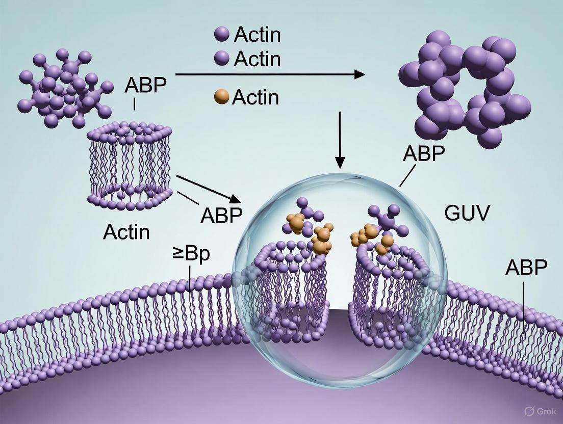
The interplay between actin networks and lipid membranes is a dynamic two-way street. A key finding from reconstitution studies is that branched actin networks nucleated by the Arp2/3 complex possess an inherent ability to sense membrane curvature [22]. These networks preferentially assemble at regions of negative or convex curvature, such as the necks of dumbbell-shaped GUVs [22]. Reciprocally, actin assembly exerts forces on the membrane. The transition from a symmetric actin shell to a polarized "comet tail" that propels a GUV is a classic example of symmetry breaking driven by polymerization-induced compressive forces [19]. This force generation is fundamental to cell-like processes such as protrusion and motility. Additionally, actin networks directly influence membrane organization by stabilizing lipid microdomains and preventing their coalescence [19]. The following diagram illustrates this complex interplay:
Achieving Precise Biochemical Regulation
The dynamic properties of actin networks—their size, turnover, and architecture—are exquisitely regulated by a suite of actin-binding proteins. A fundamental challenge is defining the minimal set of components required to reconstitute a specific process, which is a primary advantage of using purified proteins over cell extracts [20]. The precise concentrations and ratios of actors like profilin, capping protein, and NPFs determine the balance between assembly and disassembly, thereby setting the steady-state size and turnover rate of the network [20] [19]. Furthermore, the activity of regulatory proteins is itself influenced by the network architecture, creating a complex feedback loop where biochemistry and mechanics are intertwined [20]. For instance, the depolymerization and capping activity of proteins like gelsolin can be modulated by phosphoinositides such as PIP₂ and PIP₃, adding another layer of biochemical control that can be studied in reconstituted assays [23].
Giant unilamellar vesicles (GUVs) serving as minimal cell models have revolutionized our ability to study cellular processes in a controlled, bottom-up manner. The encapsulation of actin networks within GUVs represents a particularly powerful approach for reconstituting cytoskeleton-dependent functions, enabling researchers to dissect the fundamental principles governing cell shape, mechanics, and response to physical forces. This Application Note details key methodologies and quantitative findings from recent investigations into actin-encapsulating GUVs, highlighting their dual applications in mimicking cellular processes and advancing therapeutic delivery systems. By providing structured protocols and analytical frameworks, we aim to equip researchers with the tools necessary to leverage these biomimetic systems for both fundamental biological discovery and applied biotechnological development.
Core Applications and Quantitative Analysis
Mechanical Phenotyping of Actin Networks
Encapsulated actin architectures demonstrate distinct mechanical responses when subjected to external forces, enabling mechanical phenotyping of network types. Micropipette aspiration experiments reveal that network reorganization depends critically on actin-binding proteins and network geometry.
Table 1: Mechanical Responses of Actin Networks to Micropipette Aspiration
| Network Type | Composition | Aspiration Response | Network Rearrangement | Significance |
|---|---|---|---|---|
| Bundled Networks | Actin + Fascin (1:5 ratio) | Collapse and alignment along aspiration axis | Filaments reorient parallel to pipette axis | Demonstrates adaptive reorientation under flow-induced stress [14] |
| Branched-Bundled Networks | Actin + Fascin + Arp2/3 + VCA | Network resists entry into pipette | Maintains structural integrity outside pipette | Branching stabilizes architecture against deformation [14] |
| Membrane-Associated Cortex | Actin + Crowders | Stabilizes GUV against deformation | Not specified | Reinforces membrane mechanical integrity [8] |
Active Shape Dynamics and Fluctuation Analysis
The encapsulation of active cytoskeletal components generates autonomous shape dynamics that mimic living cells. When powered by ATP, these systems exhibit fluctuations that deviate significantly from thermal equilibrium.
Table 2: Quantitative Analysis of Vesicle Fluctuations in Passive vs. Active Systems
| Parameter | Passive Vesicles | Active Vesicles (MT-based) | Measurement Significance |
|---|---|---|---|
| Fluctuation Magnitude | ~1-5% R₀ | ~20% R₀ (enhanced) | Indicates non-thermal, activity-driven deformations [6] |
| Spectral Scaling | ⟨∣uₙ∣²⟩ ~ q⁻³ (bending) or ~q⁻¹ (tension) | ⟨∣uₙ∣²⟩ ~ q⁻³ (enhanced amplitude) | Active forces dominate over thermal fluctuations [6] |
| Temporal Correlation | Exponential decay, τₙ ~ (q³ + σ¯q)⁻¹ | Broken spatial-temporal relationship | Activity modifies relaxation dynamics [6] |
| Distribution Shape | Gaussian | Non-Gaussian at short timescales | Reflects non-equilibrium active processes [6] |
| Bending Rigidity | κₚₐₛₛ = 13.4 ± 2.5 kₚT | Not quantified | Baseline mechanical property [6] |
Experimental Protocols
GUV Encapsulation of Actin Networks via cDICE
The continuous droplet interface crossing encapsulation (cDICE) method enables robust encapsulation of actin networks within GUVs under physiological osmotic conditions [14] [6].
Materials:
- Lipids: DOPC, cholesterol (70:30 mol:mol) [14]
- Actin System: Purified actin, ATTO 488-labeled actin, fascin, Arp2/3 complex, His₆-tag VCA [14]
- Buffers: G-buffer (globular actin), F-buffer (polymerization) [14]
- Density Medium: Optiprep (7.5% final) to facilitate sedimentation [14]
Procedure:
- Prepare Inner Solution: Combine 5.3 μM actin with 0.53 μM ATTO 488 actin in F-buffer with 3 mM ATP. Incubate on ice for 15 minutes to pre-polymerize filaments [14].
- Initiate Network Assembly: Add fascin (1:5 ratio to actin) for bundles, or 500 nM Arp2/3 complex + 500 nM VCA for branched networks [14].
- Emulsify: Immediately emulsify the inner solution in lipid/oil mixture via pipetting to create volumetric confinement before full network assembly [14].
- Form GUVs: Dispense emulsions into rotating cDICE chamber containing osmotically matched outer aqueous solution and oil/lipid mixture. Centrifuge to form GUVs [14] [6].
- Sediment and Harvest: Utilize density difference for sedimentation. Collect GUVs for experimentation [14].
Micropipette Aspiration for Mechanical Perturbation
This protocol details the application of localized stress to actin-encapsulating GUVs to probe network mechanical properties [14].
Materials:
- Micropipettes: Standard glass capillaries (pulled with Sutter P-87 puller) [14]
- Pressure Control: High-speed pressure clamp, pressure transducer [14]
- BSA Solution: 1% for coating pipettes to prevent adhesion [14]
Procedure:
- Prepare Pipettes: Pull capillaries to create parallel-walled tips. Cut to 4-8 μm diameter using heated glass rod. Submerge in 1% BSA solution to prevent adhesion [14].
- Setup Fluidics: Mount pipette in holder. Connect three-way valve between filling syringe, micropipette, and fluid reservoir. Eliminate all air bubbles from system [14].
- Position GUV: Maintain slight positive pressure while positioning GUV near pipette tip using micromanipulator [14].
- Apply Aspiration: Induce aspiration by applying negative pressure via pressure transducer. Typical GUV diameters: 15-40 μm [14].
- Image Dynamics: Acquire timelapse images every 300 ms using confocal microscopy to track network reorganization [14].
Alternative Confinement: Microwell Fabrication
For imaging-compatible confinement without membranes, NOA-based microwells provide precise geometric control [24].
Materials:
- Optical Adhesive: NOA 81 [24]
- Mold Materials: SU8 3000 series, PDMS, epoxy resin [24]
- Passivation Reagents: Silane-PEG 30k Da, EggPC, Pluronic F-127 [24]
Procedure:
- Fabricate Molds: Create SU8 master molds using UV lithography. Generate secondary PDMS molds, then epoxy molds for durability [24].
- Cast Microwells: Polymerize NOA 81 between coverglass and epoxy mold under UV exposure [24].
- Passivate Surfaces: Treat with Silane-PEG or lipid mixtures (EggPC with ATTO 647N-labeled DOPE) to create biologically inert surfaces [24].
- Load Samples: Introduce protein reaction mixes into wells. Seal with mineral oil for long-term imaging [24].
The Scientist's Toolkit: Essential Research Reagents
Table 3: Key Reagents for GUV Actin Encapsulation Studies
| Reagent / Material | Function / Application | Example Sources |
|---|---|---|
| Purified Actin | Core filament-forming protein | Cytoskeleton, Inc. [14] |
| ATTO 488 Actin | Fluorescent labeling for visualization | Hypermol [14] |
| Fascin | Actin bundling protein | Purified in-house [14] |
| Arp2/3 Complex | Nucleates branched actin networks | Cytoskeleton, Inc. [14] |
| VCA Domain | Activates Arp2/3 complex | Purified in-house (His₆-tag) [14] |
| DOPC Lipids | Primary lipid for GUV formation | Avanti Polar Lipids [14] |
| DGS-NTA(Ni) | Membrane anchor for his-tagged proteins | Avanti Polar Lipids [14] |
| Optiprep | Density medium for GUV sedimentation | Sigma Aldrich [14] |
Visualization of Experimental Workflows and Network Responses
GUV Encapsulation and Mechanical Testing Workflow
Actin Network Responses to Mechanical Stress
GUV-encapsulated actin networks provide a versatile platform for investigating cytoskeletal mechanics and dynamics in cell-sized compartments. The methodologies outlined herein enable systematic exploration of how specific actin architectures respond to mechanical cues, revealing fundamental principles of cellular mechanobiology. These minimal systems not only advance our understanding of cell division and morphogenesis but also pave the way for engineering synthetic cellular systems with applications in targeted drug delivery and diagnostic technologies. The integration of quantitative mechanical analysis with biochemical specificity positions GUV-based models as indispensable tools for bridging molecular-level mechanisms with cellular-scale behaviors.
Best Practices for GUV Production and High-Efficiency Actin Encapsulation
In bottom-up synthetic biology, the construction of artificial cells often relies on giant unilamellar vesicles (GUVs) as foundational compartments due to their biomimetic properties and similarity in size to mammalian cells [25]. A central challenge in this field is the efficient encapsulation of complex biological machinery, particularly actin cytoskeleton networks, which are essential for achieving cellular functions like shape changes, motility, and division [26] [27]. The encapsulation efficiency and viability of these macromolecules are highly dependent on the GUV production method employed. This application note provides a detailed comparison of three core techniques—Inverted Emulsion, cDICE, and Gel-Assisted Hydration—focusing on their operational parameters, encapsulation capabilities, and suitability for actin-related research. Designed for researchers and drug development professionals, this document includes structured quantitative data, detailed experimental protocols, and essential resource guides to inform method selection and implementation.
Comparative Analysis of GUV Formation Methods
The table below summarizes the key characteristics of the three primary methods for GUV formation, enabling researchers to select the most appropriate technique based on experimental requirements.
Table 1: Comprehensive Comparison of GUV Production Methods for Actin Encapsulation
| Feature | Inverted Emulsion | cDICE (Continuous Droplet Interface Crossing Encapsulation) | Gel-Assisted Hydration |
|---|---|---|---|
| Core Principle | Phase transfer of water-in-oil emulsion droplets across a lipid-laden interface [25] | Continuous emulsion templating and transfer via a rotating chamber [26] | Swelling of a lipid film on a hydrated polymer gel surface [28] |
| Typical GUV Yield | High (with optimized parameters) [25] | High [26] | Variable, depends on lipid composition and gel [28] |
| Encapsulation Efficiency | High for large biomolecules and micron-sized particles [25] | High, "lossless encapsulation" of biomolecules [25] | Can be enhanced by combining with inverse-phase methods [28] |
| Actin Encapsulation Suitability | Excellent; used for reconstituting contractile actomyosin rings and cortices [26] [27] | Excellent; optimized for high-yield encapsulation of functional proteins like actin [26] | Suitable, especially when combined with inverse-phase methods for complexation [28] |
| Biomimetic Buffer Compatibility | Yes; works in physiological salt and buffer conditions [25] | Yes [26] | Yes; swelling buffer can contain diverse biorelevant molecules [28] |
| Membrane Oil Residue | Potential concern, but studies show no significant alteration of mechanics [25] | Potential concern, depending on oil phase used | Not applicable; oil-free method |
| Key Advantage | Rapid production, high encapsulation efficiency, compatibility with microtiter plates [25] | High throughput, monodisperse GUVs, high encapsulation precision [25] [26] | Broad compatibility with lipid compositions, gentle process (no energy input) [28] |
| Primary Limitation | Requires optimization of multiple parameters (density, centrifugation) [25] | Complex instrumental setup [25] | Lower encapsulation efficiency for macromolecules unless modified [28] |
Detailed Experimental Protocols
Optimized Inverted Emulsion Method for Actin Encapsulation
This protocol is adapted for the encapsulation of actin and associated proteins, based on optimized parameters from the literature [25] [27].
Key Reagents and Solutions:
- Lipid-in-Oil Solution: 1 mM lipid mixture (e.g., POPC with 1% biotinylated lipid for membrane anchoring) dissolved in mineral oil.
- Inner Aqueous Solution (for emulsion): Sucrose-based solution (e.g., 400 mM) containing the proteins to be encapsulated (e.g., G-actin, cross-linking proteins, neutravidin if using biotinylated anchors).
- Outer Aqueous Solution: Glucose-based solution (e.g., 350 mM) of lower density than the inner solution, to facilitate vesicle settling.
Procedure:
- Form the Lipid Monolayer Interface: In a microtiter plate well, add 100 µL of the lipid-in-oil solution. Carefully underlay this with 100 µL of the outer glucose solution. Allow the interface to incubate for 10-15 minutes at room temperature for monolayer formation.
- Prepare the Water-in-Oil Emulsion: In a separate vial, vigorously mix 20 µL of the dense inner aqueous solution (containing your biomolecules) with 100 µL of the lipid-in-oil solution to create a water-in-oil emulsion.
- Transfer Emulsion and Centrifuge: Gently pipette the emulsion and layer it on top of the interface prepared in step 1.
- Centrifuge: Place the plate in a centrifuge and spin at 2,000-5,000 x g for 10-30 minutes. The optimal speed and time must be determined empirically to maximize yield [25].
- Collect GUVs: After centrifugation, the GUVs will have settled at the bottom of the well in the outer aqueous phase. They can be carefully pipetted for observation or further experimentation.
Diagram: Workflow of the Inverted Emulsion Method
cDICE Method for High-Yield Actin Network Encapsulation
The cDICE method allows for the efficient and reproducible encapsulation of sensitive protein complexes like actin networks [26].
Key Reagents and Setup:
- Lipid Solution: 2 mg/mL lipid mixture (e.g., POPC) in an oil/ether mixture.
- Aqueous Solution: Contains all components for the internal reaction (e.g., G-actin, bundling proteins, motor proteins, polymerization buffer).
- Apparatus: A rotating chamber whose walls are pre-coated with the lipid solution. The aqueous solution is injected as droplets into the rotating chamber filled with a denser outer solution (e.g., sucrose).
Procedure:
- Prepare the Chamber: Coat the interior of a spherical rotating chamber with the lipid solution, allowing the solvent to evaporate and form a dry lipid film.
- Fill the Chamber: Add the outer aqueous solution (e.g., glucose-based) to the chamber.
- Initiate Rotation and Injection: Rotate the chamber at a constant speed (e.g., 600-1200 rpm). Inject the inner aqueous solution (containing actin and proteins) into the center of the rotating chamber. Droplets form and are stabilized by a lipid monolayer from the film.
- Vesicle Formation: As droplets travel through the lipid-laden outer solution, they cross a second interface, picking up a second lipid leaflet to become GUVs.
- Harvest GUVs: After rotation stops, collect the GUVs from the chamber.
Diagram: Conceptual Workflow of the cDICE Method
Gel-Assisted Hydration for Sensitive Lipid Compositions
This method is ideal for swelling GUVs from lipid compositions that are sensitive to mechanical stress or oil residues [28].
Key Reagents:
- Polymer Gel Substrate: A dried film of polyvinyl alcohol (PVA) or agarose on a coverglass.
- Lipid Solution: 0.5-2 mg/mL lipid mixture in an organic solvent (e.g., chloroform).
- Swelling Buffer: An aqueous buffer at the desired osmolarity and pH.
Procedure:
- Prepare the Gel Substrate: Deposit a drop of PVA or agarose solution on a coverglass and allow it to dry completely to form a thin gel film.
- Deposit Lipid Film: Spot the lipid solution onto the dried gel surface and allow the solvent to evaporate, leaving a dry lipid film.
- Hydrate: Place the coverglass in a hydration chamber, add the swelling buffer, and seal the chamber.
- Swelling: Incubate the chamber at a suitable temperature (e.g., 37-50°C) for 1-2 hours to allow GUVs to swell from the lipid film on the gel surface.
- Collect GUVs: Gently agitate the chamber and pipette the supernatant containing the detached GUVs.
The Scientist's Toolkit: Essential Research Reagents
The table below lists key reagents used in the featured experiments for actin encapsulation, along with their critical functions.
Table 2: Key Research Reagent Solutions for Actin Encapsulation in GUVs
| Reagent / Material | Function / Role in Encapsulation | Example Use-Case |
|---|---|---|
| Biotinylated Lipids (e.g., DGS-NTA(Ni)) | Provides membrane anchoring points for His-tagged proteins via neutravidin/biotin linkage [26] [27] | Anchoring His-tagged nucleators (mDia1, VCA) to the inner leaflet for cortex assembly [27] |
| F-actin Nucleators (mDia1, Arp2/3) | Controls the architecture of the encapsulated actin network (linear vs. branched) [27] | Reconstituting distinct cortex architectures to study their role in membrane deformation [27] |
| Actin Cross-linkers (Fascin, α-Actinin) | Bundles actin filaments into higher-order structures, influencing network mechanics [26] | Forming thick actin bundles and rings inside GUVs [26] |
| Membrane Anchor Proteins (Talin/Vinculin) | Links actin filaments directly to the lipid membrane, promoting cortical attachment [26] | Achieving near 100% probability of membrane-bound actin ring formation [26] |
| Sucrose/Glucose Solutions | Creates density gradients essential for phase separation and GUV settling in emulsion-based methods [25] | Forming the inner and outer aqueous phases in the inverted emulsion method [25] [27] |
Critical Parameter Optimization
Successful implementation of these methods, particularly the inverted emulsion technique, requires careful attention to several key parameters. The table below summarizes optimization findings.
Table 3: Key Optimization Parameters for the Inverted Emulsion Method [25]
| Parameter | Impact on GUV Formation | Optimization Guidance |
|---|---|---|
| Density Gradient | Crucial for driving emulsion droplets through the interface; ensures GUVs settle for easy collection [25] | Ensure inner aqueous phase (e.g., sucrose) is denser than outer phase (e.g., glucose). |
| Centrifugation Speed/Time | Directly affects yield; insufficient force prevents transfer, excessive force may disrupt vesicles [25] | Optimize between 2,000-5,000 x g for 10-30 minutes. |
| Lipid Concentration | Impacts the quality of the monolayers at the interface and around emulsion droplets [25] | Test concentrations around 0.5 - 2 mM; 1 mM is a common starting point. |
| Monolayer Incubation Time | Allows for the formation of a stable lipid monolayer at the oil-water interface [25] | Allow 10-15 minutes for monolayer formation before adding emulsion. |
| pH & Temperature | Can affect lipid packing and monolayer stability during formation [25] | Maintain a consistent, physiologically relevant pH and temperature. |
The selection of a GUV production method is a critical determinant in the success of actin encapsulation experiments. The Inverted Emulsion method offers a robust balance of high encapsulation efficiency and operational simplicity, making it an excellent choice for many laboratories seeking to incorporate cytoskeletal components. The cDICE technique, while requiring more specialized equipment, provides superior control over vesicle size and is highly effective for encapsulating complex, functional protein networks with high reproducibility. Finally, Gel-Assisted Hydration presents a gentle, oil-free alternative, ideal for studies where membrane composition is paramount and potential oil residue is a concern. By leveraging the optimized protocols and comparative data provided herein, researchers can strategically select and implement the most appropriate methodology to advance their work in synthetic biology and drug development.
The reconstitution of cytoskeletal components, such as actin networks, within giant unilamellar vesicles (GUVs) represents a significant stride in bottom-up synthetic biology, aiming to emulate critical cellular functions like mechanical stability and shape changes in artificial cells [17]. The encapsulation of proteins into GUVs presents a unique challenge, as standard formation methods can be inefficient with complex biological mixtures. This protocol details the inverted emulsion technique, optimized for the high-yield encapsulation of actin and its binding proteins, enabling the study of actin's mechanical role under cell-like confinement [29] [17]. By modifying established protocols with key parameters like prolonged waiting time and chloroform addition, researchers can achieve efficient GUV formation and protein encapsulation, paving the way for investigating actin dynamics and membrane-protein interactions in a controlled, cell-free environment [29].
Materials
Research Reagent Solutions
The following table lists essential materials required for the inverted emulsion method to encapsulate actin in GUVs.
| Item | Function/Explanation |
|---|---|
| 1,2-dioleoyl-sn-glycero-3-phosphocholine (DOPC) | A neutral phospholipid used to form the primary lipid bilayer of the GUVs, providing a synthetic membrane structure [30]. |
| Chloroform | An organic solvent added to the lipid-dispersed oil to enhance GUV formation efficiency by promoting lipid aggregation and improving adsorption at the oil-water interface [29]. |
| Mineral Oil | The oil phase used to create the water-in-oil emulsion, which is a critical first step in the inverted emulsion method. |
| Sucrose Solution | A dense sugar solution used for the inner aqueous phase (e.g., containing actin); its density aids in the subsequent phase transfer of GUVs [29]. |
| Glucose Solution | A less dense sugar solution used for the outer aqueous phase; the density difference between inner and outer solutions helps in sedimenting and cleaning the formed GUVs. |
| G-Actin (Monomeric) | The globular, monomeric form of actin to be encapsulated. It can be polymerized into F-actin inside the GUVs to study its mechanical effects [17]. |
| MgCl₂ Solution | A salt solution used to promote the polymerization of G-actin into filamentous F-actin inside the GUVs [17]. |
| Ion Carrier A23187 | A molecule that facilitates the transport of Mg²⁺ ions across the lipid bilayer to trigger actin polymerization inside the GUVs [17]. |
| Fluorescently Labelled Lipid (e.g., Rhodamine-PE) | A lipid conjugated to a fluorophore (like Rhodamine B) that is incorporated in small amounts into the bilayer to enable visualization of the GUV membrane via fluorescence microscopy [30]. |
Equipment
- Plasma oxidizer [30]
- Orbital shaker [30]
- Incubator (capable of maintaining 22-23°C and 45°C) [29] [30]
- Desiccator/vacuum [30]
- Confocal or epifluorescence microscope [29] [30]
- Microcentrifuges
- Vortex mixer [30]
- Round-bottom glass test tubes
- Clinical centrifuge
Methods
Experimental Workflow for Actin Encapsulation
The following diagram outlines the complete encapsulation process, from lipid film preparation to final observation.
Step-by-Step Protocol
Lipid Preparation and Monolayer Formation
- Lipid Solution Preparation: Dissolve purified lipids (e.g., DOPC) in a mixture of 90-95% mineral oil and 5-10% chloroform (Δ = 5-10%) to create a 1-2 mM lipid solution. The inclusion of chloroform is critical, as it significantly enhances GUV formation and encapsulation efficiency [29].
- Form Primary Emulsion: In a glass tube, combine the lipid-oil solution with the inner aqueous solution (e.g., G-actin in sucrose buffer). The total volume ratio should be approximately 1:1. Vortex the mixture vigorously for 1-2 minutes to form a stable water-in-oil (w/o) emulsion, where the aqueous droplets are surrounded by a lipid monolayer.
- Monolayer Incubation: Let the primary emulsion rest for a prolonged waiting time (τ = 120 minutes). This extended period is crucial for the lipid monolayer to fully stabilize at the oil-water interface, which directly increases the fraction of larger GUVs (>5 µm) in the final population [29].
GUV Formation and Harvesting
- Form GUVs via Centrifugation: Carefully layer the incubated emulsion on top of a dense sucrose solution in a centrifuge tube. Subject the tube to gentle centrifugation (e.g., 1,500 × g for 15-30 minutes). This forces the emulsion droplets through the interface, where a second lipid monolayer assembles, forming a bilayer and releasing the GUVs into the lower aqueous solution [29].
- Collect GUVs: After centrifugation, a pellet of GUVs will be visible. Carefully collect these GUVs from the bottom of the tube using a pipette. They can be washed by resuspending in an isotonic glucose solution to remove excess oil and non-encapsulated material.
Internal Actin Polymerization
- To polymerize the encapsulated G-actin into F-actin inside the GUVs, add MgCl₂ (to a final concentration of 2 mM) and the ion carrier A23187 (to a final concentration of 1 µM) to the GUV suspension [17]. The ion carrier is essential for transporting Mg²⁺ ions across the lipid bilayer to initiate the polymerization reaction within the GUV lumen.
- Incubate the GUVs at room temperature (22-23°C) for 30-90 minutes to allow for complete actin filament formation [29] [17].
Key Optimization Parameters
The table below summarizes the quantitative effects of two key protocol parameters on GUV formation, based on statistical analysis [29].
| Parameter | Total GUV Number | Encapsulation Efficiency | Number of GUVs >5µm | Fraction of GUVs >5µm |
|---|---|---|---|---|
| Chloroform Addition (Δ) | Significant Increase (p < 0.001 for 0% vs. 10%) [29] | Significant Increase (p < 0.001 for 0% vs. 5% and 0% vs. 10%) [29] | Significant Increase (p ≈ 0.001 for 0% vs. 10%) [29] | No significant impact (p ≈ 0.08) [29] |
| Waiting Time (τ) | No significant post-hoc difference [29] | No significant impact (p ≈ 0.19) [29] | No significant post-hoc difference [29] | Significant Increase (p ≈ 0.02 for 0 min vs. 120 min) [29] |
Expected Results and Analysis
Successful encapsulation will yield GUVs visible via phase-contrast microscopy. When fluorescently labeled actin is used, confocal microscopy will reveal its distribution inside the GUVs. In the presence of MgCl₂ and the ion carrier, F-actin will accumulate near the GUV membrane, leading to a measurable change in the vesicle's mechanical properties [17]. The functionality of encapsulated actin-binding proteins can be assessed by their ability to cross-link, bundle, or sever the actin network, observable as distinct morphological changes in the actin architecture within the GUVs.
Mechanical Property Assessment
The mechanical effect of encapsulated actin can be quantified by analyzing vesicle deformability.
As illustrated, GUVs containing polymerized F-actin will show significantly increased resistance to deformation compared to those containing only monomeric G-actin or empty GUVs, confirming the mechanical reinforcement provided by the actin cortex [17].
Application Notes
- Troubleshooting: Low GUV yield can often be remedied by increasing the chloroform percentage (Δ) in the lipid-dispersed oil and ensuring a sufficient waiting time (τ) for monolayer maturation [29].
- Actin Polymerization Control: The use of an ion carrier is crucial for initiating actin polymerization from within the GUVs, as Mg²⁺ ions cannot passively cross the lipid bilayer efficiently [17].
- Composition Flexibility: This protocol can be adapted for various lipid compositions, including charged lipids, and for co-encapsulating other proteins or biomolecules to reconstruct more complex cytoskeletal processes [29] [30].
The construction of biomimetic membranes that replicate the fluidity and stability of natural cell membranes is a cornerstone of synthetic biology research, particularly in the context of building minimal cells from giant unilamellar vesicles (GUVs). A primary challenge in this field is the successful encapsulation and interaction of actin networks with the lipid bilayer, a process essential for reconstituting cell-like behaviors such as shape changes, motility, and division [19]. The lipid composition of the bilayer directly governs its physical properties, including phase separation, fluidity, and mechanical stability, which in turn orchestrate the spatial organization and dynamic remodeling of the encapsulated cytoskeleton [19] [18]. This Application Note provides detailed protocols and compositional guidelines to optimize GUV lipid bilayers for studies focusing on actin encapsulation and membrane-cytoskeleton interactions.
Lipid Composition and Membrane Properties
The careful selection of lipid species is paramount for controlling membrane behavior. Ternary mixtures containing phospholipids, sphingolipids, and cholesterol are widely used to induce liquid-ordered (Lo) and liquid-disordered (Ld) phase coexistence, mimicking the lipid raft heterogeneity of the native plasma membrane [31] [19].
Quantitative Effect of Lipid Composition on Membrane Fluidity
Membrane fluidity can be quantitatively assessed by measuring the translational diffusion coefficient (Dₜ) of lipid probes. The table below summarizes how different lipid compositions and phases influence the diffusion of a Bodipy-labeled cholesterol analog (Bdp-Chol) [31].
Table 1: Translational Diffusion of a Lipid Probe in Different Membrane Environments
| Lipid Phase/Composition | Translational Diffusion Coefficient, Dₜ (×10⁻⁸ cm²/s) | Key Characteristics |
|---|---|---|
| Liquid-Disordered (Ld) Phase | ( 7.4 \pm 0.3 ) | Formed by unsaturated lipids like DOPC; high fluidity. |
| Liquid-Ordered (Lo) Phase | ( 5.0 \pm 0.2 ) | Cholesterol-rich with sphingomyelin; lower fluidity, biologically relevant. |
| DOPC/Cholesterol/SM (25/50/25) | Lo: ( 5.0 \pm 0.2 ) (Bdp-Chol) | Preferential partitioning of Bdp-Chol into the Lo phase (Kp=1.88). |
Compositions for Phase Separation and Actin Encapsulation
Specific lipid molar ratios have been successfully employed to generate phase-separated GUVs that also support the encapsulation and polymerization of actin networks. The following table outlines two validated compositions [18].
Table 2: Optimized Lipid Compositions for Phase-Separated GUVs with Actin Encapsulation
| Lipid Components | Composition 1: Actin Bundles (mol %) | Composition 2: Actin Networks (mol %) | Function of Lipid Components |
|---|---|---|---|
| DOPC (Dioleoylphosphatidylcholine) | 17.5 | 33.5 (DOPC+DOPG) | Unsaturated lipid, forms Ld phase [19]. |
| DPPC (Dipalmitoylphosphatidylcholine) | 31.5 | 30 | Saturated lipid, contributes to Lo phase formation. |
| Cholesterol | 30 | 30 | Regulates membrane fluidity and promotes Lo phase [31] [19]. |
| Biotinyl CAP PE | 1 | 1.5 | Provides binding sites for streptavidin-linked proteins (e.g., NPFs). |
| DOPG/DPPG | 21 (DOPG+DPPG) | - | Anionic lipids, can influence protein binding via charge interactions. |
| Texas-Red DHPE / Atto655-DOPE | Trace (0.001 mol%) | Trace (0.001 mol%) | Fluorescent labels for membrane visualization. |
Experimental Protocols
Protocol 1: One-Pot Emulsion Transfer for Actin Encapsulation in Phase-Separated GUVs
This protocol is adapted for high encapsulation efficiency while maintaining the activity of cytoskeletal proteins [18].
Materials:
- Lipids: DOPC, DPPC, Cholesterol, DOPG, DPPG, Biotinyl CAP PE, Atto655-DOPE (or Texas-Red DHPE).
- Proteins: G-actin (unlabeled, Atto488-labeled, biotinylated).
- Buffers and Reagents: Chloroform, decane, mineral oil, Ficoll70, BSA, GTP (for FtsZ), Tris-HCl, sucrose, KCl, MgCl₂, DTT, ATP.
- Equipment: Bath sonicator, centrifuge, vacuum desiccator, glass vials, 96-well imaging plates.
Procedure:
- Lipid Mixture Preparation: a. In a glass vial, combine lipids in chloroform to achieve Composition 1 or 2 from Table 2. b. Evaporate the chloroform under a stream of N₂ gas to form a thin lipid film. c. Place the vial under vacuum in a desiccator for 30 minutes to remove residual solvent. d. Re-disperse the dried lipid film in a mixture of decane and mineral oil. e. Sonicate the lipid-in-oil mixture at ~50°C for 30 minutes and incubate at 37°C before use.
Inner Solution Preparation (Actin Bundle Mixture): a. Prepare a 10 µL actin master mix on ice, protected from light, containing: - 86% G-actin - 10% Atto488-actin - 4% biotinylated actin b. The final concentration of the actin mix in the encapsulation solution should be approximately 35 µM.
GUV Formation via Emulsion Transfer: a. Gently layer the protein-containing inner solution (from step 2) on top of the prepared lipid-in-oil mix. b. Centrifuge the tube at elevated temperatures (optimized at 37°C to promote phase separation while retaining protein activity). c. After centrifugation, collect the formed GUVs from the bottom of the tube for immediate imaging or further experimentation.
Diagram 1: Emulsion transfer workflow for GUV production.
Protocol 2: Microfluidic Platform for Actin-Based Membrane Remodeling Studies
This protocol is designed for high-throughput, sequential observation of actin-induced membrane remodeling on immobilized GUVs [19].
Materials:
- Microfluidic Chips: Polydimethylsiloxane (PDMS) chambers.
- Passivation Reagents: PLL-PEG to prevent protein and lipid adsorption.
- Actin Polymerization Components: Actin, Arp2/3 complex, profilin, capping protein (CP), streptavidin-pVCA-His (SpVCA-His).
- Buffers: Polymerization buffer (sucrose, Tris, KCl, MgCl₂, DTT, ATP, β-casein).
Procedure:
- Microfluidic Chamber Preparation: a. Treat PDMS microfluidic chambers with PLL-PEG to create a non-adhesive surface. b. Load the passivated chamber with a population of pre-formed, biotinylated GUVs. c. Immobilize dozens of GUVs in designated traps within the chamber.
Actin Network Assembly: a. Flush the chamber with a solution containing the actin polymerization machinery: SpVCA-His (binds to biotinylated lipids), actin, Arp2/3 complex, profilin, and CP. b. Incubate to allow the formation of a branched actin network on the inner or outer surface of the GUVs. c. The actin shell generates compressive forces, leading to symmetry breaking and polarization, which can propel the GUVs in a manner reminiscent of Listeria monocytogenes.
Observation and Analysis: a. Monitor the dynamics of membrane deformation and the concurrent stabilization of lipid domains by the actin network in real-time. b. The platform allows for the sequential modification of the protein composition to dissect the roles of individual factors.
Diagram 2: Microfluidic assay for actin remodeling.
The Scientist's Toolkit: Research Reagent Solutions
Table 3: Essential Reagents for GUV-Actin Reconstitution Experiments
| Reagent Category | Specific Examples | Function in the Experiment |
|---|---|---|
| Lipids for Bilayer Structure | DOPC, DPPC, Sphingomyelin, Cholesterol [31] [19] | Form the lipid bilayer; regulate phase separation (Lo/Ld) and fluidity. |
| Functionalized Lipids | Biotinyl CAP PE, Ni-NTA lipids [19] | Provide specific binding sites for recruiting proteins (e.g., NPFs) to the membrane. |
| Fluorescent Lipid Probes | Atto655-DOPE, Texas-Red DHPE [18] | Enable visualization of the membrane and its lipid domains via fluorescence microscopy. |
| Cytoskeletal Proteins | G-actin (labeled & unlabeled), Biotinylated Actin [18] | The core building blocks for reconstituting actin networks and bundles. |
| Actin-Binding Proteins (ABPs) | Arp2/3 Complex, Profilin, Capping Protein (CP) [19] [32] | Control actin network nucleation, elongation, branching, and capping. |
| Nucleation Promoting Factors (NPFs) | Streptavidin-pVCA-His (SpVCA) [19] | Activate the Arp2/3 complex to initiate branched actin network formation at the membrane. |
| Membrane Crowding Agents | Ficoll70, BSA [18] | Mimic the crowded intracellular environment, promoting protein polymerization and network formation. |
Concluding Remarks
The protocols and compositions detailed herein provide a robust foundation for advancing GUV-based research into membrane-cytoskeleton interactions. The integration of precisely controlled lipid compositions with efficient encapsulation techniques allows for the creation of increasingly sophisticated minimal cell models. Future work will benefit from coupling these biomimetic membranes with optogenetic tools, such as the OptoVCA system [32], for unparalleled spatiotemporal control over actin dynamics. This integrated approach promises to deepen our understanding of how physical membrane properties govern biological function, paving the way for applications in targeted drug delivery and synthetic cell engineering.
The reconstitution of biomimetic actin networks inside giant unilamellar vesicles (GUVs) represents a cornerstone of the bottom-up synthetic biology approach to understanding cellular mechanics. By recreating increasingly complex cytoskeletal architectures in defined, cell-sized compartments, researchers can dissect the fundamental principles governing how specific protein components self-organize and generate mechanical forces. Incorporating actin-crosslinking proteins such as fascin and α-actinin is a critical advancement for progressing from simple encapsulated actin filaments to sophisticated networks that mimic the structural diversity found in living cells. These crosslinkers dictate the mesoscale architecture of the resulting actin assemblies, which in turn determines the mechanical properties of the minimal cell and its capacity for shape change and force generation. This protocol details methodologies for incorporating fascin to build structurally complex and mechanically functional actin networks within GUVs, enabling the investigation of network reorganization under mechanical stress and the emergent structures arising from crosslinker competition and sorting.
Research Reagent Solutions: Essential Components for Actin Network Reconstitution
Table 1: Key reagents for reconstituting crosslinked actin networks in GUVs.
| Reagent Category | Specific Examples & Concentrations | Primary Function in Reconstitution |
|---|---|---|
| Actin & Polymerization Components | 5-5.3 µM actin (purified or commercial) [14] [33], 0.53 µM ATTO 488-labeled actin [14], Polymerization Buffer (F-buffer) [14] | Forms the primary filamentous (F-actin) network scaffold; fluorescent label enables visualization. |
| Crosslinking Proteins | Fascin (0.25-2.5 µM) [33], α-Actinin (0.5-1.5 µM) [33] | Bundles actin filaments into specific architectures; fascin creates tight bundles, while α-actinin facilitates clustering. |
| Branching Network Components | Arp2/3 complex (500 nM) [14], His6-tag VCA (500 nM) [14] | Nucleates branched actin networks, mimicking the dendritic architecture of lamellipodia. |
| Lipid Components for GUVs | DOPC, Cholesterol (70/30 mol/mol) [14], DGS-NTA(Ni) [14] | Forms the GUV lipid bilayer; cholesterol provides fluidity and stability; DGS-NTA(Ni) enables membrane-protein linkage. |
| Experimental Buffers & Solutions | General Actin Buffer (G-buffer) [14], Osmotically Matched Outer Solution (~200 mOsm) [14] [33], OptiPrep (5-7.5%) [14] [33] | Maintains protein stability and GUV integrity through osmotic balance; OptiPrep aids in GUV sedimentation. |
Quantitative Foundations: Architectural and Mechanical Outcomes
Encapsulation experiments with different crosslinkers have yielded quantitative relationships between protein composition, confinement geometry, and the resulting network architecture. The tables below summarize key empirical findings that can guide experimental design and expectation-setting.
Table 2: Network architecture outcomes based on crosslinker identity and GUV size.
| Crosslinker Condition | Small GUVs (7-12 µm) | Medium GUVs (12-16 µm) | Large GUVs (>16 µm) |
|---|---|---|---|
| α-Actinin Alone | Primarily single actin rings [34] [35] | Mixed rings and networks [34] [35] | Primarily peripheral aster clusters and complex networks [34] [35] |
| Fascin Alone | Rings or single protruding bundles [34] [35] | More complex structures and bundles [34] [35] | Network of rigid bundles, often deforming the GUV [34] [35] [33] |
| α-Actinin & Fascin Combined | Reduced ring probability [34] [35] | Increased network/ring-network structures [34] [35] | High probability of central aster formation with sorted crosslinkers [34] [35] |
Table 3: Fascin-actin bundle characteristics and mechanical responsiveness.
| Parameter | Observation/Measurement | Experimental Context & Citation |
|---|---|---|
| Inter-filament Distance | ~12 nm [36] [37] | Cryo-EM structure of fascin crossbridge. |
| Bundle Packing | Hexagonal arrays [36] [37] | Observed in vitro and in filopodia. |
| Maximum Bundle Size | ~20-30 filaments [36] [37] | Limits bundle growth, maintaining mechanical compliance. |
| Response to Aspiration | Collapse and alignment along aspiration axis [14] | Micropipette aspiration of fascin-bundled networks in GUVs. |
| Response to Aspiration (Branched Bundles) | Network remains intact outside pipette [14] | Micropipette aspiration of Arp2/3 + fascin networks in GUVs. |
Experimental Protocols
Protocol 1: Encapsulation of Crosslinked Actin Networks in GUVs via cDICE
This protocol describes the encapsulation of actin bundles into GUVs using the continuous droplet interface crossing encapsulation (cDICE) method [14] [33], suitable for reconstituting both singular and competing crosslinker systems.
I. Preparation of Inner Solution 1. Actin Polymerization: Reconstitute fluorescent filamentous actin by incubating 5.3 µM actin and 0.53 µM ATTO 488-labeled actin in F-buffer supplemented with 3 mM ATP on ice for 15 minutes [14]. 2. Crosslinker Addition: * For fascin-bundled networks, add fascin to the polymerized actin at a 1:5 molar ratio to actin (e.g., ~1 µM) and mix gently [14]. * For branched-bundled networks, first prepare actin as above, then add 500 nM Arp2/3 complex and 500 nM His6-tag VCA to the solution [14]. * For crosslinker competition studies, add both α-actinin (e.g., 0.5-1.5 µM) and fascin (e.g., 0.25-2.5 µM) to the actin solution [33]. 3. Final Preparation: Include 7.5% (v/v) OptiPrep in the final inner solution to facilitate subsequent GUV sedimentation. Immediately proceed to emulsification.
II. GUV Formation via cDICE 1. Setup: Mount a custom 3D-printed cDICE chamber on a benchtop stir plate and rotate at 1,200 rpm [33]. 2. Solution Layering: Pipette an outer aqueous solution (e.g., 200 mM glucose, osmotically matched to the inner solution) into the chamber. Then, carefully add the lipid-oil mixture (e.g., 70% DOPC, 30% cholesterol in silicone/mineral oil) on top. Centrifugal force will create a planar oil-water interface [14] [33]. 3. Emulsification and Vesiculation: Pipette the inner solution prepared in Step I into the rotating chamber. The inner solution will be emulsified into droplets that cross the lipid-monolayer interface at the oil-water boundary, forming GUVs enclosed by a lipid bilayer [14].
Protocol 2: Probing Network Mechanics via Micropipette Aspiration
This protocol is used to apply localized mechanical stress to GUVs and observe the subsequent rearrangement of the encapsulated actin network, revealing architecture-dependent mechanical responses [14].
I. Micropipette Preparation 1. Fabrication: Pull standard glass capillaries using a pipette puller (e.g., Sutter P-87) to create a fine tip. 2. Trimming: Use a heated glass rod to manually cut the pipette tip to a final diameter of 4-8 µm. 3. Coating: Submerge the pipette in a 1% BSA solution to prevent GUV adhesion during experiments.
II. System Setup and Aspiration 1. Mounting: Secure the BSA-coated micropipette onto a micropipette holder connected to a fluidic line and a pressure control system (e.g., a high-speed pressure clamp and transducer). 2. Priming: Use a filling syringe to fill the entire micropipette line and connected reservoir with a solution that is osmotically matched to the GUV's outer solution. Ensure all air bubbles are eliminated. 3. GUV Selection and Aspiration: Locate a GUV of interest (15-40 µm diameter) under an inverted microscope. Using a micromanipulator, bring the micropipette tip into close proximity. Apply a slight positive pressure initially to prevent unintended aspiration, then use the pressure transducer to apply a defined negative pressure to aspirate the GUV [14].
III. Imaging and Analysis 1. Data Acquisition: Use confocal microscopy (e.g., with a 40X/1.3 NA objective) to acquire time-lapse images of the actin fluorescence (e.g., every 300 ms) during the aspiration process. 2. Analysis: Process images using software like ImageJ. Quantify network rearrangement by analyzing fluorescence intensity profiles or tracking bundle orientation before, during, and after aspiration [14].
Visualization of Workflows and Molecular Mechanisms
Experimental Workflow for GUV Reconstitution and Mechanical Interrogation
The following diagram illustrates the end-to-end experimental process for creating minimal cell models and probing their mechanical properties.
Molecular Sorting Mechanism of Competing Crosslinkers
This diagram depicts the nanoscale mechanism by which α-actinin and fascin sort into distinct domains within a confined GUV environment.
Fascin's Molecular Mechanism of Actin Crosslinking
This diagram illustrates the structural plasticity of fascin that enables it to form tightly packed actin bundles, a key mechanism for building network complexity.
The reconstitution of cytoskeletal components within giant unilamellar vesicles (GUVs) has established a powerful platform for creating minimal cell models. These systems have been instrumental in deciphering the fundamental principles by which the actin cytoskeleton confers mechanical integrity, shape, and dynamic responses to living cells [14] [21]. However, the true complexity of a eukaryotic cell arises from the interplay between the cytoskeleton and other functional modules, most notably the cell nucleus. This integration is critical for processes such as mechanotransduction, where physical forces are converted into biochemical signals that can ultimately influence gene expression. This application note, framed within the broader context of GUV-based actin research, outlines the experimental rationale and detailed methodologies for co-encapsulating actin networks with other functional modules. We focus particularly on creating a synthetic nucleus, providing a protocol to advance minimal cell models toward greater physiological relevance for researchers and drug development professionals.
Current State of GUV Encapsulation Research
The field has made significant progress in encapsulating and studying isolated cytoskeletal networks. Research has demonstrated that actin network architecture—whether bundled, branched, or cross-linked—distinctly determines the mechanical phenotype of the GUV.
- Architecture-Dependent Mechanical Response: Studies using micropipette aspiration have shown that fascin-bundled actin networks collapse and align along the aspiration axis, whereas branched networks (nucleated by the Arp2/3 complex) resist entry into the pipette, revealing fundamental differences in how network architecture responds to localized stress [14].
- Crosslinker-Driven Emergent Structures: Co-encapsulating actin with different cross-linkers, such as α-actinin and fascin, leads to the self-assembly of complex architectures like rings and asters. Strikingly, these cross-linkers spontaneously sort into separate domains within the structures, a process driven by their distinct molecular sizes and the bending energy of actin filaments [34].
- Active Force Generation with Microtubules: Moving beyond actin, the encapsulation of an active network of microtubules and molecular motors (kinesin) has been achieved. This active gel generates internal forces that drive large, non-equilibrium shape fluctuations and traveling deformations in the GUV membrane, mimicking dynamic cellular processes [6].
Table 1: Key Findings from Advanced GUV Encapsulation Studies
| Encapsulated System | Key Finding | Implication for Minimal Cells |
|---|---|---|
| Actin Bundles (Fascin) vs. Branched Networks (Arp2/3) | Network-specific reorganization under micropipette aspiration [14] | Mechanical response is tunable via network architecture. |
| Actin + α-Actinin + Fascin | Self-sorting of cross-linkers and formation of peripheral/central asters [34] | Confinement can drive emergent protein sorting and complex structure formation. |
| Microtubules + Kinesin Motors | Active forces induce large, non-equilibrium membrane fluctuations [6] | Coupling between internal active matter and the membrane can drive cell-like dynamics. |
Experimental Rationale and Objectives
The logical next step in the evolution of minimal cell models is the integration of multiple, interactive functional modules. A primary objective is the co-encapsulation of a cytoskeletal network with a synthetic nucleus. This would enable the investigation of coupled processes such as:
- Nuclear Mechanosensing: Studying how cytoskeleton-generated forces or changes in GUV shape deform a synthetic nucleus and potentially affect processes mimicking gene regulation.
- Cytoskeletal Assembly Nucleated by the Nucleus: Exploring the role of the nucleus as a physical scaffold or organizational center for the cytoskeleton, similar to its role in cells. This application note provides a detailed protocol to establish this advanced system, building directly upon the well-developed methods for actin and microtubule encapsulation.
Protocol: Co-encapsulation of Actin Networks and a Synthetic Nucleus
This protocol describes the formation of GUVs containing an actin network and a DNA-based synthetic nucleus using the continuous droplet interface crossing encapsulation (cDICE) method [6] [34].
Reagents and Materials
Table 2: Research Reagent Solutions for Co-encapsulation
| Reagent / Material | Function / Role | Example Source / Specification |
|---|---|---|
| Lipids (DOPC, Cholesterol, DGS-NTA(Ni)) | Form the GUV membrane bilayer; DGS-NTA(Ni) allows for His-tagged protein binding [14]. | Avanti Polar Lipids |
| Actin (from porcine brain) | Primary structural filament for internal cytoskeleton [14] [34]. | Cytoskeleton, Inc. |
| ATTO 488-conjugated Actin | Fluorescent labeling of actin networks for visualization [14]. | Hypermol |
| DNA (e.g., λ-phage DNA) | Acts as a crowding agent and nucleus analog [34]. | Highly purified, high molecular weight |
| PEG-based Aqueous Two-Phase System (ATPS) | Forms coacervate droplets that serve as a synthetic nucleus [34]. | Polyethylene Glycol (PEG) & Dextran |
| Fascin and/or α-Actinin | Actin cross-linkers to create specific bundled network architectures [14] [34]. | Purified recombinant |
| Arp2/3 Complex & His₆-VCA | Nucleates branched actin networks from the membrane [14]. | Cytoskeleton, Inc. |
| OptiPrep | Density gradient medium; aids in GUV sedimentation and purification [14]. | Sigma-Aldrich |
| cDICE Apparatus | Instrument for high-yield GUV formation with controlled encapsulation [6]. | Custom-built or commercial |
Step-by-Step Procedure
Step 1: Preparation of the "Inner Solution"
- Polymerize Actin Filaments: Incubate 5.3 µM actin (including 10% ATTO 488-actin) in 1x F-buffer (e.g., from Cytoskeleton, Inc.) supplemented with 3 mM ATP on ice for 15 minutes [14].
- Form Synthetic Nucleus Coacervate: In a separate tube, mix a PEG-dextran ATPS with DNA. Gently vortex to form DNA-rich coacervate droplets. The DNA acts as a nucleoid and crowding agent.
- Combine Solutions: Gently mix the polymerized actin and coacervate suspension.
- Add Cross-linkers: To define the actin network architecture, add one of the following:
- Add Density Agent: Include 7.5% (v/v) OptiPrep to the final inner solution to facilitate subsequent GUV sedimentation [14].
Step 2: GUV Formation via cDICE
- Prepare Lipid Mixture: Dissolve DOPC and cholesterol (e.g., 70/30 mol/mol) in mineral oil/silicon oil (20/80% v/v) to form the lipid-oil mixture [14] [6].
- Prepare Outer Aqueous Solution: Prepare a sucrose solution osmotically matched (~200 mOsm) to the inner solution.
- Set up cDICE Chamber: Add the outer aqueous solution and the lipid-oil mixture to the rotating cDICE chamber. Centrifugal forces will create planar layers [6].
- Create Emulsion and Form GUVs: Just before adding to the cDICE chamber, emulsify the inner solution by pipetting it into a small volume of the lipid-oil mixture. This creates volumetric confinement prior to full network assembly. Immediately dispense this emulsion into the rotating cDICE chamber [14]. The rotation period (e.g., 30-60 minutes) allows GUVs to form at the interface and settle.
Step 3: GUV Harvesting and Imaging
- Collect GUVs: After rotation, carefully collect the GUVs from the bottom of the cDICE chamber.
- Wash/Exchange Buffer: Transfer GUVs into an isotonic glucose solution via gentle centrifugation or dialysis to remove non-encapsulated material and aid in GUV settling for microscopy.
- Image on Confocal Microscope: Place GUVs on a glass-bottom dish and image using a spinning disk confocal microscope. Use a 40x or 60x oil-immersion objective. Acquire fluorescence images for actin (ATTO 488) and the synthetic nucleus (if fluorescently labeled), along with brightfield or DIC images to visualize the GUV membrane.
The following workflow diagram summarizes the key experimental steps for GUV formation and encapsulation.
Characterization and Analysis
Once GUVs containing actin and the synthetic nucleus are formed, their structural and mechanical properties can be characterized using the following techniques.
Micropipette Aspiration
This technique applies localized stress to probe the mechanical response of the internal network and its interaction with the synthetic nucleus [14].
- Setup Preparation: Pull glass capillaries to a tip diameter of 4-8 µm. Fill the micropipette and reservoir with a solution osmotically matched to the GUV's outer solution. Mount the pipette on a micromanipulator and maintain a slight positive pressure to prevent accidental aspiration [14].
- Aspiration and Imaging: Bring the pipette tip near a GUV. Apply a controlled negative pressure using a pressure transducer. Simultaneously acquire timelapse images (e.g., every 300 ms) using both fluorescence (to visualize actin and nucleus) and brightfield (to track the membrane) channels [14].
- Expected Outcomes: You may observe actin bundle alignment (in the case of fascin) or resistance to entry (in the case of branched networks). A key observation would be whether the aspiration force transmits to and deforms the synthetic nucleus.
Flicker Spectroscopy for Active Fluctuations
For GUVs exhibiting dynamic shape changes, flicker spectroscopy quantifies the non-equilibrium activity.
- Contour Extraction: From high-frame-rate videos of the GUV equator, extract the membrane contour ( R(\phi, t) ) over time [6].
- Fourier Mode Decomposition: Decompose the contour into Fourier modes ( uq(t) ) using the equation: [ R(\phi, t) = R0 \left( 1 + \sum{q}^{q{\max}} uq(t) e^{iq\phi} \right) ] where ( R0 ) is the mean radius and ( q ) is the wave number [6].
- Power Spectrum Analysis: Calculate the power spectrum ( \langle |uq|^2 \rangle ). Passive vesicles follow ( \langle |uq|^2 \rangle \approx \frac{k_B T}{\kappa} \frac{1}{q^3 + \bar{\sigma}q} ), while active GUVs show a significant increase in fluctuation magnitude across all modes, indicating force generation from the encapsulated active matter [6].
Table 3: Quantitative Analysis of GUV Mechanics from Literature
| Analysis Method | Measured Parameter | Representative Finding | Reference | ||
|---|---|---|---|---|---|
| Micropipette Aspiration | Network reorganization under flow | Fascin-bundled networks align; branched networks resist entry. | [14] | ||
| Flicker Spectroscopy | Fluctuation power spectrum ( \langle | u_q | ^2 \rangle ) | Active GUVs show ~10x increased fluctuations (( \approx q^{-3} ) decay). | [6] |
| AC Electric Field Deformation | GUV deformability index | Actin cortex greatly dampens electrodeformation vs. actin-free GUVs. | [21] |
Troubleshooting and Technical Notes
- Low Encapsulation Efficiency: Ensure the inner solution is emulsified immediately after adding cross-linkers to pre-confine the components before full network assembly in the cDICE chamber [14].
- GUV Adhesion to Pipette: Pre-treat micropipettes with a 1% BSA solution to prevent non-specific adhesion during aspiration experiments [14].
- Network Architecture Not As Expected: Titrate the molar ratios of cross-linkers to actin. For example, a fascin:actin ratio of 1:5 promotes bundle formation, while specific concentrations of Arp2/3 and VCA (e.g., 500 nM each) are needed for branched networks [14] [34].
- Minimizing Batch Variability: Use purified proteins from reliable commercial sources or standardize in-house purification protocols. Aliquoting and freezing proteins at -80°C preserves activity.
Solving Common Problems in GUV Actin Encapsulation: A Troubleshooting Guide
Within the field of bottom-up synthetic biology and biophysical research, the reconstitution of complex biological systems inside Giant Unilamellar Vesicles (GUVs) represents a powerful approach for studying cell-like processes in a controlled environment. A particularly active research area focuses on encapsulating actin cytoskeleton networks to investigate cell mechanics, motility, and shape dynamics in synthetic cells [4] [38] [39]. The successful reconstitution of these dynamic systems hinges on the production of high-quality, defect-free GUVs with high encapsulation efficiency. While several methods exist for GUV formation, techniques derived from emulsion transfer principles, especially continuous droplet interface crossing encapsulation (cDICE), have shown remarkable success for encapsulating sensitive protein systems [4] [38]. However, a significant challenge persists: lab-to-lab variability and poor reproducibility often hinder robust GUV formation. Emerging evidence indicates that two critical parameters—the precise control over the waiting time between lipid-oil dispersion preparation and its use, and the incorporation of chloroform additives—can dramatically influence GUV quality and formation efficiency. This Application Note examines the impact of these parameters within the context of actin cytoskeleton research, providing structured quantitative data, optimized protocols, and practical guidance to enhance experimental outcomes.
Results and Discussion
The Critical Role of Timing and Chloroform in Lipid Dispersion Stability
The preparation of the lipid-in-oil dispersion is a foundational step in emulsion-based GUV formation methods like cDICE. Research indicates that the temporal stability of this dispersion and the inclusion of chloroform are determining factors for producing defect-free GUVs.
Table 1: Impact of Lipid-Oil Dispersion Storage Conditions on GUV Quality
| Storage Condition | Macroscopic Appearance | Turbidity (A350) | Interfacial Tension Kinetics | Resulting GUV Quality |
|---|---|---|---|---|
| Used immediately after sonication | Transparent | 0.10 ± 0.05 | Standard decrease | High yield of defect-free, quasi-spherical GUVs |
| Stored at 4°C for ≤ 24 hours | Slightly cloudy | Not Reported | Not Reported | Acceptable for many applications [4] |
| Prepared without humidity control | Opaque | 0.42 ± 0.10 | Faster decrease | Fluorescent lipid aggregates, membrane pockets, budding structures |
The data in Table 1 underscores that the lipid-in-oil dispersion is a time-sensitive reagent. The optimal protocol involves using the mixture immediately after preparation, with a strict maximum storage time of 24 hours at 4°C [4]. Beyond this window, the dispersion degrades, leading to suboptimal GUVs. This temporal sensitivity is linked to the microscopic organization of lipids in the oil phase. When preparations are performed without controlling environmental humidity, water contamination causes the dispersion to become opaque, indicating the formation of lipid aggregates [38]. These aggregates alter the lipid adsorption kinetics at the oil-water interface, as measured by pendant drop experiments, which in turn disrupts the proper zipping of a uniform bilayer during vesicle formation [38].
Chloroform Additives and Environmental Control Are Key for Reproducibility
The inclusion of chloroform in the lipid-in-oil dispersion has been identified as a key factor for improving the reliability of the cDICE method. A chloroform-based dispersion, when prepared in a humidity-free environment such as a glove box, yields transparent mixtures and is essential for the robust formation of clean, defect-free GUVs without visible lipid pockets or budding structures [38].
Environmental control is paramount. Humidity causes the chloroform-lipid-oil mixture to become opaque and increases variability in lipid adsorption kinetics. Performing the preparation in a glovebox and conducting cDICE experiments in a dehumidified room (30–40% relative humidity) are critical steps to ensure reproducible production of high-quality GUVs year-round [38]. This controlled environment prevents water contamination that would otherwise interfere with the lipid organization and the subsequent bilayer formation process.
Consequences for Actin Cytoskeleton Reconstitution
The quality of the GUV membrane directly impacts downstream biological reconstitutions. For studies of actin cytoskeleton dynamics, defects or residual membrane materials in suboptimal GUVs can aberrantly nucleate actin polymerization or disrupt the geometry of cortex formation. The use of a freshly prepared, chloroform-optimized lipid dispersion is therefore not merely a technical detail but a prerequisite for observing inherent cytoskeleton behaviors, such as the curvature-sensing capabilities of branched actin networks nucleated by Arp2/3 complex [22] or the CP-controlled switching between membrane protrusion and invagination [39].
Experimental Protocols
Optimized Protocol: Preparation of Lipid-In-Oil Dispersion with Chloroform
This protocol is adapted from established cDICE methods and highlights the critical steps involving chloroform and timing [4] [38].
1. Preparation of Oil-Lipid Mixture (Perform in a Fume Hood)
- Materials:
- Chloroform
- Lipid stocks in chloroform (e.g., DOPC, Cholesterol, Rhodamine-PE)
- Silicone oil
- Mineral oil
- Two 15 mL glass vials
- Vortex mixer
- Bath sonicator
- Procedure:
- Add 0.5 mL of chloroform to a 15 mL glass vial.
- To the chloroform, add the desired lipids. Example for a standard membrane: 88 μL of 25 mg/mL DOPC, 9.3 μL of 50 mg/mL cholesterol, and 5 μL of 1 mg/mL Rhodamine-PE. The final mole fractions will be ~69.9% DOPC and 30% cholesterol [4].
- In a second glass vial, pipette 7.2 mL of silicone oil and 1.8 mL of mineral oil.
- Mix the oils by vortexing at maximum speed (3200 RPM) for 10 s.
- Add the oil mixture to the vial containing the lipid-chloroform solution and immediately vortex for 10–15 s at maximum speed. The mixture will appear slightly cloudy.
- Sonicate the lipid-in-oil dispersion in a bath sonicator (80 W, 40 kHz) at room temperature for 30 minutes.
- Use the mixture immediately for best results, or store it at 4°C for a maximum of 24 hours [4].
2. Environmental Control (Critical Step)
- For maximum reproducibility and the highest GUV quality, the entire preparation of the lipid-in-oil dispersion (steps 1.1 to 1.6) should be performed inside a low-humidity glove box [38].
- The cDICE experiment and GUV formation should be carried out in a dehumidified room (30–40% relative humidity) [38].
Alternative Protocol: GUV Formation via Polyacrylamide Gel Hydration
For researchers unable to implement the humidity-controlled cDICE setup, gel-assisted hydration methods provide a robust alternative, though with generally lower encapsulation efficiency. This method does not involve chloroform or oil dispersions, thus bypassing the associated timing constraints [40] [30].
- Functionalize Glass Cover Slips with APTES and glutaraldehyde to covalently bond the polyacrylamide (PAA) gel [30].
- Prepare PAA Gel by mixing acrylamide and bis-acrylamide to the desired stiffness (e.g., 4 kPa) and pore size. Degas the solution before polymerization.
- Cast and Dry the Gel onto the functionalized cover slips, then dry the gels in vacuo.
- Deposit Lipids by evenly dispersing a lipid film of choice onto the dried gel surface.
- Hydrate with Buffer by adding the aqueous solution (e.g., PBS or sucrose solution) containing the molecules to be encapsulated onto the gel-lipid hybrid film. Allow GUVs to form overnight.
- Collect GUVs by gently pipetting the solution above the gel.
The Scientist's Toolkit
Table 2: Essential Research Reagent Solutions for cDICE-based GUV Formation
| Reagent / Material | Function / Role | Example & Comments |
|---|---|---|
| Chloroform | Solvent for initial lipid dissolution; critical additive for forming a homogeneous lipid-oil dispersion. | Sigma-Aldrich, Cat# 67-66-3. Handle in a fume hood [4]. |
| Lipid-Oil Dispersion | Forms the lipid monolayers at water-oil interfaces for bilayer assembly during cDICE. | Composition: DOPC, Cholesterol, fluorescent lipid (Rhodamine-PE) in silicone/mineral oil [4]. |
| DOPC (Lipid) | Primary phospholipid component providing membrane structure and fluidity. | Avanti Polar Lipids, Cat# 850375C [4]. |
| Cholesterol | Modulates membrane fluidity and stability; 30 mol% is physiologically relevant and optimal for cDICE [4]. | Avanti Polar Lipids, Cat# 700100P (powder) [4]. |
| cDICE Rotation Chamber | 3D-printed chamber that rotates to stratify fluids and form GUVs via centrifugal force. | Made from clear resin (Formlabs) [4]. |
| Fused Silica Capillary Tubing | For injecting the aqueous encapsulant solution; larger diameters (e.g., 100 μm) prevent clogging. | Alternative to pulled glass capillaries for improved reliability [38]. |
| Dehumidifier / Glove Box | Controls ambient humidity during lipid-oil prep and GUV formation, crucial for reproducibility. | Prevents water contamination in lipid-oil dispersion, ensuring consistent results [38]. |
Workflow and Decision Framework
The following diagram illustrates the optimized experimental workflow for high-efficiency GUV formation, integrating the critical parameters of waiting time and environmental control.
The efficient encapsulation of functional actin cytoskeletons in GUVs requires meticulous attention to the preparation of lipid-in-oil dispersions. The integration of chloroform as an additive and the strict control of the waiting time between dispersion preparation and use are not merely minor protocol details but are central to achieving high yields of defect-free GUVs. By adhering to the optimized protocols and environmental controls outlined in this Application Note, researchers can significantly enhance the reproducibility and reliability of their experiments, thereby accelerating progress in the bottom-up reconstitution of cellular machinery and the development of advanced synthetic cells.
Ensuring Unilamellarity and Controlling Vesicle Size and Polydispersity
In the pursuit of constructing minimal cells and biomimetic systems, the encapsulation of cytoskeletal proteins like actin within giant unilamellar vesicles (GUVs) represents a significant frontier. The physicochemical properties of these vesicles—specifically their unilamellarity, size, and size distribution (polydispersity)—are critical for the faithful reconstitution of cellular processes. These parameters directly impact the fidelity of cytoskeletal-membrane interactions, the accuracy of quantitative measurements, and the overall biological relevance of the synthetic system. This Application Note synthesizes contemporary methodologies to reliably produce GUVs with defined characteristics, providing a structured framework for researchers in synthetic biology and drug development.
Quantitative Comparison of GUV Production Methods
Selecting an appropriate fabrication method is the primary determinant of success in GUV-based research. The following table summarizes key performance metrics for three prominent techniques, enabling an evidence-based selection process.
Table 1: Performance Metrics of Advanced GUV Fabrication Methods
| Method | Reported Vesicle Size Range | Key Strength | Encapsulation Efficiency | Best Suited Application |
|---|---|---|---|---|
| Emulsion Transfer (Droplet Transfer) [7] [41] | 0.1 µm to >1 µm | High encapsulation efficiency for proteins and particles [7] | High [7] [41] | Encapsulation of valuable cargo (e.g., cytoskeletal proteins) [7] |
| PCP-Assisted Hydration [42] | Broad range (4°C-45°C) | High yield under physiological ionic strength [42] | Enables encapsulation of complex systems (e.g., cell-free mixtures) [42] | Building synthetic cells under physiological conditions [42] |
| Modified cDICE Method [9] | Tunable size | Precise control over vesicle size [9] | Data not specified | Applications requiring tight control over GUV dimensions [9] |
Detailed Experimental Protocols
Emulsion Transfer for Actin Encapsulation in Phase-Separated GUVs
This protocol is adapted from a established method for the reconstitution of cytoskeletal proteins, such as actin, inside phase-separated GUVs, making it ideal for studying cytoskeletal-membrane interactions [7].
3.1.1 Reagent Preparation
- Lipid Solution (LS): Prepare a lipid mixture in oil (e.g., mineral oil) to yield phase separation. A common combination is DOPC, cholesterol, and sphingomyelin. Dissolve lipids to a final concentration of approximately 0.2-3 mM [7] [41].
- Inner Solution (IS): 240 mM sucrose solution containing the cytoskeletal protein(s) for encapsulation (e.g., actin) [41]. The sucrose creates an osmotic gradient.
- Outer Solution (OS): An equiosmolar glucose solution (e.g., 240 mM). The density difference between the sucrose-filled GUVs and the glucose-based OS aids in vesicle collection [41].
3.1.2 Step-by-Step Procedure
- Form Water-in-Oil Emulsion: Vigorously mix the LS with the IS (containing actin) to form a stable emulsion where aqueous droplets, stabilized by a lipid monolayer, are dispersed in the oil phase [7] [41].
- Form LS/OS Interface: In a separate tube, gently layer the OS on top of a small volume of LS. Allow the interface to equilibrate.
- Transfer Emulsion: Carefully pour the emulsion from Step 1 on top of the pre-formed LS/OS interface.
- Centrifuge: Centrifuge the tube at elevated temperatures (ideally 37°C to maintain protein activity) to force the water droplets across the interface. During this crossing, the second lipid monolayer forms, resulting in the creation of unilamellar vesicles [7].
- Collect GUVs: After centrifugation, the GUVs will be contained in the bottom aqueous (OS) phase. Carefully collect this fraction for imaging or further experimentation [41].
Diagram 1: Emulsion transfer method workflow.
PCP-Assisted Hydration for Physiological Conditions
This method uses polymer-coated nanocellulose paper (PCP) as a nanostructured substrate to achieve high GUV yields in physiologically relevant buffers, which is typically challenging [42].
3.2.1 Reagent Preparation
- Lipid Film: Prepare a lipid film from your chosen lipid composition using standard methods (e.g., drying down from chloroform).
- Polymer-Coated Nanocellulose Paper (PCP): Use or fabricate PCP as the hydration substrate.
- Hydration Buffer: A physiological ionic strength buffer (e.g., containing salt, ultralow-gelling agarose, hyaluronic acid, or other soluble polymers) [42].
3.2.2 Step-by-Step Procedure
- Substrate Preparation: Place a piece of PCP in a suitable hydration chamber.
- Apply Lipid Film: Hydrate the lipid film directly on the surface of the PCP with the chosen hydration buffer. The nanoscale curvature of the cellulose fibers and the osmotic pressure from the dissolving polymer act synergistically to promote membrane budding and GUV formation, even in the presence of salt [42].
- Incubate: Allow the system to incubate for a period (e.g., 1 hour) at a controlled temperature (works across 4°C-45°C) to facilitate vesicle assembly.
- Harvest GUVs: Gently agitate the chamber to release the assembled GUVs from the PCP substrate into the buffer for collection.
Diagram 2: PCP-assisted hydration workflow.
The Scientist's Toolkit: Essential Research Reagents
Successful GUV formation and actin encapsulation rely on a carefully selected set of materials. The following table details key reagents and their specific functions in the experimental workflow.
Table 2: Essential Reagents for GUV Actin Encapsulation
| Reagent/Category | Specific Examples | Function in Protocol |
|---|---|---|
| Phospholipids | DOPC, Sphingomyelin, Cholesterol [7] | The fundamental building blocks of the vesicle membrane. Composition determines phase behavior (e.g., liquid-ordered/disordered domains) and fluidity [7]. |
| Oils for LS | Mineral Oil, Silicone Oil AR20 [41] | Solvent for dissolving lipids to form the lipid solution (LS). Choice influences monolayer formation and GUV yield [41]. |
| Osmotic Agents | Sucrose, Glucose [41] | Create density and osmotic gradients. Sucrose in IS and glucose in OS help in GUV collection and maintain membrane integrity [41]. |
| Encapsulation Cargo | Actin, FtsZ, Cell-Free Expression Mixtures [7] [42] | The active biomolecules to be enclosed within the GUV lumen, enabling the study of cytoskeletal dynamics in confinement [7]. |
| Specialized Substrates | Polymer-Coated Nanocellulose Paper (PCP) [42] | Provides nanoscale curvature that synergizes with polymer osmosis to boost GUV yield under physiological salt conditions [42]. |
Concluding Remarks
The methodologies outlined herein provide robust and reproducible pathways for generating GUVs with controlled unilamellarity, size, and low polydispersity. The Emulsion Transfer method excels in high-efficiency encapsulation of sensitive proteins like actin, while PCP-Assisted Hydration breaks new ground for constructing synthetic cells under physiological conditions. By leveraging the quantitative data and detailed protocols provided, researchers can systematically select and optimize a GUV production strategy, thereby laying a solid foundation for advanced research in minimal cell engineering and membrane biophysics.
Preventing Residual Oil Contamination in Emulsion-Based Methods
In the field of bottom-up synthetic biology, giant unilamellar vesicles (GUVs) serve as foundational models for synthetic cells and are indispensable for reconstituting cellular processes, such as the cytoskeleton-membrane interactions fundamental to cell mechanics and morphology [4] [21]. Emulsion-based formation techniques, particularly continuous droplet interface crossing encapsulation (cDICE) and related phase transfer methods, have emerged as powerful tools for the high-efficiency encapsulation of biologically relevant components like actin networks and actin-binding proteins (ABPs) within GUVs [4] [43]. These methods enable the creation of a cell-like confined environment that is crucial for studying the dynamic assembly of cytoskeletal structures [4].
A paramount challenge persistent in these emulsion-based techniques is the issue of residual oil contamination. Residual oil droplets or an incorporated oil layer within the GUV membrane can significantly alter membrane physical properties, including fluidity, elasticity, and permeability [43]. For research focused on actin cytoskeleton reconstitution, where the precise interplay between the membrane and the encapsulating actin network determines fundamental mechanical phenotypes, these alterations pose a severe experimental confound [21]. Oil contamination can obscure the true mechanics of membrane-actin interactions, lead to inconsistent experimental results, and ultimately invalidate the biological relevance of the reconstituted system. Therefore, developing robust protocols to prevent oil contamination is not merely a technical refinement but a critical necessity for producing high-fidelity, biomimetic GUVs for quantitative biological research.
Key Mechanisms of Emulsion Destabilization and Oil Contamination
To effectively prevent oil contamination, it is essential to understand the fundamental mechanisms of emulsion instability that can lead to its occurrence. Emulsions are inherently thermodynamically unstable systems, and their breakdown pathways directly impact the purity of the final GUV preparation [44].
- Coalescence: This process involves the merging of two or more dispersed oil droplets to form a larger droplet. During GUV formation via phase transfer, uncontrolled coalescence of the W/O emulsion droplets at the interface can trap oil, leading to incorporation into the budding GUV membrane or as internal droplets [44].
- Flocculation: This refers to the aggregation of dispersed droplets into clusters without the loss of their individual identity. While potentially reversible, flocculation accelerates gravitational separation and increases the likelihood of subsequent coalescence events, thereby raising the risk of oil contamination in the final GUV sample [44].
- Ostwald Ripening: This phenomenon is driven by the difference in solubility between small and large droplets. Molecular diffusion of the dispersed phase (oil) from smaller to larger droplets can occur, especially if the oil phase has non-negligible water solubility. This can alter the size distribution of emulsion droplets and affect the consistency of GUV formation [44].
The stability of the initial W/O emulsion is significantly influenced by the properties of its components. A higher viscosity in the continuous phase can slow down the movement of droplets, reducing the frequency of collisions and thereby enhancing stability against coalescence and flocculation [44]. Furthermore, the nature of the emulsifier—its effectiveness in reducing interfacial tension and forming a robust interfacial layer—is a critical factor in preventing these destabilization mechanisms [44].
Quantitative Analysis of Factors Affecting Oil Contamination
The following tables summarize key parameters that influence residual oil contamination, based on data from the literature.
Table 1: Oil and Lipid Phase Composition Effects on GUV Purity and Yield
| Parameter | Impact on Oil Contamination | Optimal Range / Type | Experimental Notes |
|---|---|---|---|
| Oil Type | Determines solubility, viscosity, and tendency for retention. | Mineral oil/Silicone oil mixtures [4]; Squalene, Liquid paraffin [43] | 1-Octanol leads to poor GUV yields and vesicular aggregates [43]. |
| Lipid Composition | Affects monolayer rigidity and completeness at the interface. | DOPC with 20-30 mol% Cholesterol [4] | Cholesterol improves membrane stability and fluidity [4]. Additive lipids (e.g., PEG-lipids) can reinforce the membrane [43]. |
| Lipid Dispersion | Incomplete lipid dissolution leads to unstable monolayers. | Sonicated for 30 min at 40 kHz [4] | The lipid-in-oil mix should be used immediately or stored at 4°C for a max of 24 hours [4]. |
Table 2: Emulsion Handling and Centrifugation Parameters
| Parameter | Impact on Oil Contamination | Optimal Range / Type | Experimental Notes |
|---|---|---|---|
| Emulsification Method | Determines initial droplet size and stability. | Vortex mixing, hand tapping [43] | Ultrasonication can generate radical species that damage lipids and biomolecules [43]. |
| Volume Ratio (Inner:Oil) | Influences droplet size and packing. | < 30% [43] | A lower volume of inner solution produces smaller GUVs [43]. |
| Centrifugation Force & Time | Drives phase transfer; excessive force can promote coalescence. | Requires optimization [43] | The inner solution must be denser than the outer solution [43]. |
| Outer Solution Osmolarity | Affects GUV integrity and oil retention. | Matched osmolarity with inner solution [43] | Use of glucose (outer) and sucrose (inner) solutions is common to facilitate post-formation GUV sedimentation [43]. |
Optimized Experimental Protocols
cDICE Method for High-Yield, Low-Contamination Actin GUVs
This protocol, adapted from [4], is specifically designed for the rapid encapsulation of cytoskeletal proteins with high efficiency and reduced oil contamination.
A. Preparation of Lipid-in-Oil Mixture
- Procedure: In a fume hood, pipette 0.5 mL of chloroform into a 15 mL glass vial. Add lipids to achieve a final mole fraction of ~70% DOPC, 30% cholesterol, and a trace amount (e.g., 0.5-1 mol%) of a fluorescently tagged lipid (e.g., rhodamine PE) for visualization [4].
- Oil Preparation: In a separate vial, prepare a mixture of silicone oil and mineral oil (e.g., a 7.2:1.8 mL ratio). Add this oil mixture to the lipid-chloroform solution and immediately vortex at maximum speed for 10-15 seconds. The resulting dispersion will appear slightly cloudy [4].
- Sonication: Sonicate the lipid-in-oil dispersion in a bath sonicator (80 W, 40 kHz) at room temperature for 30 minutes to ensure proper dispersion. Use the mixture immediately or store at 4°C for a maximum of 24 hours [4].
B. Vesicle Generation via cDICE
- Setup: Mount a 3D-printed shaft and cDICE chamber on a benchtop stir plate. Set the rotational speed to 1200 RPM to create a stable lipid-covered interface [4].
- Protein Preparation: Prepare the actin and ABP solutions separately. For actin, prepare a 1–10 µM solution in G-buffer, with a portion (e.g., 10%) being fluorescently labelled. Initiate polymerization by adding F-buffer and incubating on ice for 15 minutes before adding crosslinkers (e.g., fascin, α-actinin) at the desired molar ratio. Keep the solution on ice until encapsulation to slow polymerization [4].
- Emulsification & Encapsulation: Emulsify the protein solution of interest in the prepared lipid-oil mixture to create lipid-monolayered droplets. Add these droplets into the rotating cDICE chamber. The droplets will pass through the second lipid monolayer at the water/oil interface, forming GUVs within seconds [4].
- Collection: Collect the GUVs from the chamber. The entire process from start to collection can be completed in 15–20 minutes, which is critical for capturing time-dependent processes like actin network assembly [4].
W/O Emulsion Centrifugation Method
This method, detailed in [43], is a robust laboratory-scale technique for encapsulating various materials.
- Emulsion Formation: Add the inner aqueous solution (containing the material to be encapsulated) to the lipid-containing oil phase. The volume ratio of the inner solution to the oil phase should be less than 30%. Emulsify the mixture via mechanical agitation (vortex mixing, gentle stirring) [43].
- Layering and Centrifugation: Gently layer the resulting W/O emulsion onto an outer aqueous solution that is denser than the emulsion's continuous phase. The osmolarity of the inner and outer solutions should be matched to avoid defects. Centrifuge the biphasic system to transfer the emulsion droplets across the oil-water interface [43].
- GUV Harvesting: After centrifugation, the GUVs will be collected in the outer aqueous solution (lower phase). They can be pipetted out for immediate use or further purification [43].
The Scientist's Toolkit: Essential Reagents and Materials
Table 3: Research Reagent Solutions for Emulsion-Based GUV Formation
| Item | Function/Description | Example Sources / Comments |
|---|---|---|
| DOPC (1,2-dioleoyl-sn-glycero-3-phosphocholine) | Primary phospholipid for forming the GUV bilayer, providing a fluid membrane matrix. | Avanti Polar Lipids [4] |
| Cholesterol | Modulates membrane fluidity and stability. Incorporation at 20-30 mol% is typical for physiological relevance and GUV robustness [4]. | Avanti Polar Lipids [4] |
| Silicone Oil & Mineral Oil | Forms the oil phase for creating the W/O emulsion and the interface for GUV formation. Specific mixtures are used to tune density and viscosity [4] [43]. | Acros Organics, Sigma-Aldrich [4] |
| Actin (from rabbit muscle) | Core cytoskeletal protein for reconstitution of structural networks inside GUVs. | Cytoskeleton Inc. [4] |
| Actin-Binding Proteins (ABPs) | Proteins that regulate actin network architecture (e.g., cross-linkers like fascin, α-actinin). | Various, including homemade preparations [4] |
| Density Gradient Medium (e.g., Optiprep) | Used to adjust the density of aqueous solutions for controlled centrifugation and GUV purification. | Sigma-Aldrich [4] |
Workflow and Contamination Control Diagram
The following diagram illustrates the optimized GUV formation workflow and pinpoints critical control points for preventing oil contamination.
GUV Formation and Quality Control
Preventing residual oil contamination is a cornerstone of reliable GUV research, especially in the nuanced field of actin cytoskeleton reconstitution. By understanding the mechanisms of emulsion instability and meticulously optimizing parameters—such as oil and lipid composition, emulsification methods, and centrifugation conditions—researchers can consistently produce high-fidelity, oil-free GUVs. The protocols and guidelines outlined here provide a concrete pathway to achieving this goal, ensuring that the mechanical and biochemical data derived from GUV-based experiments accurately reflect the properties of the reconstituted biomimetic system and not artifacts of the preparation process.
In the rapidly advancing field of synthetic biology, the reconstitution of actin-based cytoskeletal networks inside giant unilamellar vesicles (GUVs) represents a powerful bottom-up approach to understanding cell mechanics and morphology. This research relies fundamentally on maintaining the structural integrity and biochemical activity of actin proteins throughout experimental procedures. The challenges are substantial—actin is a dynamic protein sensitive to its biochemical environment, and its encapsulation within cell-sized compartments introduces complexities related to confined volumes, component limitations, and controlled polymerization. This application note details essential protocols and buffer considerations for preserving actin functionality in GUV-based research, providing scientists with standardized methods to ensure experimental reproducibility and reliability in cytoskeletal reconstitution studies.
Actin Biochemistry and Stability Fundamentals
Actin exists in a dynamic equilibrium between monomeric (G-actin) and filamentous (F-actin) states, a process regulated by nucleotide binding (ATP/ADP), ionic conditions, and associated binding proteins. Maintaining this dynamic capability in vitro requires precise biochemical environments. The polymerization process initiates with a lag phase during which nucleation occurs, followed by rapid elongation and eventual steady-state equilibrium. In confined environments like GUVs, this process is further influenced by volume limitations, which can alter reaction kinetics and deplete available monomers and regulatory factors.
Proper buffer composition is critical for mimicking physiological conditions and preserving actin's native conformation. Key factors include pH stability, ionic strength for polymerization initiation, nucleotide cofactors (ATP) for energy-dependent dynamics, and protective agents against oxidation and denaturation. Deviations from optimal conditions can lead to protein aggregation, loss of polymerization capability, or aberrant filament morphology, ultimately compromising experimental outcomes in membrane-cytoskeleton interaction studies.
Essential Buffer Compositions and Reagents
Table 1: Standard Buffer Formulations for Actin Biochemistry
| Buffer Type | Composition | Function | Application Notes |
|---|---|---|---|
| General Actin Buffer (G-Buffer) | 0.2 mM CaCl₂, 0.2 mM ATP, 0.5 mM DTT, 2 mM Tris, pH 7.5 | Maintains G-actin in monomeric state; prevents spontaneous nucleation | Store on ice; use within 24 hours for optimal results; DTT prevents oxidation [14] |
| Polymerization Buffer (F-Buffer) | 50 mM KCl, 2 mM MgCl₂, 1 mM ATP, 0.1 mM DTT, 10 mg/mL β-casein, 165 mM sucrose, 1 mM Tris, pH 7.4 | Provides ionic conditions for F-actin formation; osmotically matches GUV interior | Adjust sucrose concentration to match GUV internal osmolarity (~200 mOsm) [19] |
| Electroformation Buffer | 200 mM sucrose, 2 mM Tris, pH 7.4, 200 mOsm | Creates optimal environment for GUV formation | Osmolarity critical for proper vesicle formation and stability [19] |
Table 2: Key Research Reagents for Actin-GUV Studies
| Reagent | Function | Experimental Role |
|---|---|---|
| Profilin | Accelerates actin-bound nucleotide exchange; promotes actin polymerization | Enhances actin turnover; regulates filament growth rates [19] |
| Arp2/3 Complex | Nucleates branched actin networks; creates dendritic architectures | Mimics cellular actin nucleation; enables comet tail formation [19] [20] |
| Capping Protein (CP) | Binds filament barbed ends; prevents assembly/disassembly | Stabilizes filament length; controls network architecture [19] |
| Streptavidin-pVCA-His | Nucleation promoting factor (NPF); activates Arp2/3 complex | Links actin polymerization to membrane via NTA-lipids [19] |
| Fascin | Crosslinks actin filaments into parallel bundles | Creates filopodia-like structures; stabilizes networks [14] |
| DGS-NTA(Ni) Lipids | Membrane anchor for his-tagged proteins (e.g., NPF) | Couples actin polymerization to membrane interface [19] [14] |
Actin Encapsulation Workflow in GUVs
The successful reconstitution of functional actin networks inside GUVs requires a meticulously coordinated workflow that maintains protein activity throughout the process. The following diagram illustrates the critical stages from protein preparation to final analysis:
Detailed Methodological Protocols
Actin Preparation and Quality Control
Monomer Preparation and Storage
- Reconstitute lyophilized actin according to manufacturer specifications in pre-chilled G-Buffer
- Clarify monomer solution by centrifugation at 150,000 × g for 30 minutes at 4°C to remove aggregates
- Determine concentration spectrophotometrically using extinction coefficient ε₂₉₀ = 26,600 M⁻¹·cm⁻¹
- Aliquot into working concentrations (typically 5-10 μM) and flash-freeze in liquid nitrogen
- Store at -80°C; avoid repeated freeze-thaw cycles (maximum 2-3 cycles recommended)
Polymerization Quality Assessment
- Prepare F-actin by adding 1/10 volume 10× F-Buffer to G-actin solution
- Incubate at room temperature for 30 minutes, then stabilize on ice for 15 minutes
- Verify polymerization efficiency by viscometry or sedimentation assays
- For fluorescence microscopy, label a portion (typically 5-10%) with ATTO 488 or similar fluorophore
- Confirm filament morphology by TIRF microscopy when possible [20]
GUV Production via cDICE Method
Lipid Mixture Preparation
- Prepare stock solution of DOPC:cholesterol (70:30 mol/mol) in chloroform
- Add functional lipids: 0.5-1% DGS-NTA(Ni) for his-tagged protein attachment, 0.1% biotinylated lipids if needed
- Evaporate organic solvent under nitrogen stream to form thin lipid film
- Hydrate with appropriate aqueous solution and subject to vacuum desiccation for 2 hours
Continuous Droplet Interface Crossing Encapsulation (cDICE)
- Prepare inner solution: 5.3 μM actin, 0.53 μM ATTO 488-actin in F-Buffer supplemented with 3 mM ATP
- Include 7.5% Optiprep density medium to facilitate GUV sedimentation [14]
- Emulsify inner solution in lipid/oil mixture via vigorous pipetting before full network assembly
- Transfer emulsion to rotating cDICE chamber containing outer aqueous solution (200 mOsm)
- Centrifuge at 2000-4000 × g for 45-60 minutes at controlled temperature (20-25°C)
- Collect GUVs from top interface and transfer to observation chambers [14] [6]
GUV Quality Assessment
- Examine under phase-contrast microscopy for unilamellar structure and size uniformity
- Confirm membrane integrity by exclusion of external dyes
- Verify osmolarity matching by spherical morphology under isotonic conditions
- Assess functionalization by binding of fluorescent his-tagged proteins to NTA lipids
Microfluidic Immobilization and Analysis
Device Preparation and Passivation
- Fabricate PDMS microfluidic chambers using standard soft lithography
- Treat with oxygen plasma for 30-60 seconds to activate surface
- Apply PLL-PEG passivation solution (0.1-1 mg/mL) for 1 hour to prevent protein adsorption [19]
- Rinse thoroughly with passivation buffer to remove excess reagent
- Load GUV suspension at controlled flow rate (10-50 μL/min)
- Immobilize dozens to hundreds of GUVs in trapping arrays for parallel observation [19]
Actin Network Assembly on Membranes
- Pre-treat NTA-functionalized GUVs with his-tagged nucleation factors (e.g., SpVCA-His)
- Introduce actin monomer solution (4-6 μM) with polymerization regulators
- Include profilin (1-2 μM), Arp2/3 complex (50-500 nM), and capping protein (10-100 nM) [19]
- Maintain constant ATP regeneration system (2 mM ATP) for sustained dynamics
- Image network formation every 30-300 seconds using confocal or TIRF microscopy [19] [14]
Activity Preservation: Critical Considerations
Troubleshooting Common Issues
Problem: Inconsistent Actin Polymerization
- Potential causes: ATP depletion, oxidation, or improper ionic strength
- Solutions: Fresh ATP supplementation, increased DTT concentration (0.5-1 mM), verify Mg²⁺ and K⁺ concentrations
Problem: GUV Lysis During Encapsulation
- Potential causes: Osmolarity mismatch, mechanical stress, or lipid composition issues
- Solutions: Precisely measure osmolarity of all solutions (±5 mOsm), optimize centrifugation force, adjust cholesterol content for membrane stability
Problem: Non-specific Protein Adsorption
- Potential causes: Inadequate surface passivation
- Solutions: Extend PLL-PEG treatment time, include β-casein (1-5 mg/mL) in buffers, test alternative passivation agents [19]
Advanced Considerations for Complex Assays
For studies involving phase-separated membranes or mechanical perturbation, additional factors require attention. When working with liquid-ordered/liquid-disordered membrane domains, ensure temperature control during experiments as domain formation is temperature-sensitive [19]. For micropipette aspiration studies, include oxygen-scavenging systems to minimize photodamage during prolonged observation [14]. When studying actin-membrane interactions with BAR domain proteins (e.g., BIN1, IRSp53), maintain appropriate PI(4,5)P2 concentrations in membranes and account for protein-induced membrane curvature generation [45].
Maintaining actin protein activity throughout GUV encapsulation experiments demands meticulous attention to buffer composition, handling protocols, and quality control checkpoints. The methods outlined herein provide a standardized framework for reconstituting functional actin networks within biomimetic membranes, enabling robust investigation of cytoskeleton-membrane interactions. As the field progresses toward increasingly complex synthetic cellular systems, these foundational protocols will serve as essential tools for uncovering the physical mechanisms underlying cellular shape changes and mechanical adaptation.
Optimizing Encapsulation Efficiency for Charged Molecules and Physiological Buffers
The quest to build minimal synthetic cells and biomimetic model systems using giant unilamellar vesicles (GUVs) has intensified in recent years, particularly for researchers investigating actin cytoskeleton dynamics in cell-like environments. A central challenge in this field remains the efficient encapsulation of charged molecules and biologically active components in physiologically relevant buffers. Conventional GUV production techniques often fail when confronted with physiological salt conditions or charged lipid compositions, leading to low encapsulation efficiencies (EE) and compromised biological activity. This application note synthesizes recent methodological advances to provide optimized protocols for achieving high encapsulation efficiency of charged molecules, specifically focusing on the context of actin cytoskeleton research. We present quantitative data on encapsulation performance and detailed workflows that enable researchers to create more realistic and functional minimal cell models.
Methodological Comparison: Overcoming Limitations of Conventional Techniques
Limitations of Traditional GUV Formation Methods
Traditional methods for GUV formation face significant limitations when working with charged molecules and physiological buffers:
- Gentle Hydration: While simple and accessible, this method requires extended timeframes (up to several days) and works only with restricted lipid compositions and ionic conditions [46]. The encapsulation efficiency is typically low and variable.
- Electroformation: Although faster than gentle hydration, electroformation struggles with physiological buffers containing salts and charged lipid mixtures [46]. The application of electrical fields can potentially damage sensitive biomolecules, and the method can induce unintended lipid asymmetry in charged membranes [47].
- Emulsion-based Methods: While offering high encapsulation efficiencies, these techniques often require specialized microfluidic equipment and may leave residual oil phases in the membrane that can interfere with biological function [46].
Advanced Techniques for Enhanced Encapsulation
Recent innovations have addressed these limitations through gel-assisted and emulsion-transfer approaches:
- Gel-Assisted Swelling: This method involves swelling lipid precursor films on dried polyvinyl alcohol (PVA) gel surfaces, enabling GUV formation with a wide range of lipid compositions and buffer conditions without damaging electrical inputs [46]. Compared to agarose-based gel methods, PVA gels minimize polymer contamination and optimize lipid distribution at the hydration interface.
- Emulsion Transfer Methods: Techniques like continuous droplet interface crossing encapsulation (cDICE) utilize water-in-oil emulsions as templates for bilayer formation, enabling highly efficient encapsulation even at physiological salt conditions [6] [14]. These methods are particularly valuable for encapsulating complex biological assemblies like cytoskeletal networks.
Table 1: Comparison of GUV Preparation Methods for Charged Molecules and Physiological Buffers
| Method | Optimal Use Case | Encapsulation Efficiency | Key Advantages | Limitations |
|---|---|---|---|---|
| PVA Gel-Assisted Swelling | Charged lipids, physiological buffers | Moderate to High | Wide lipid compatibility, no electrical damage, minimal polymer contamination | Requires polymer surface preparation |
| cDICE & Emulsion Transfer | Actin networks, cytoskeletal assemblies | High (can be >80%) | Excellent encapsulation efficiency, works with physiological buffers | Requires specialized equipment, potential oil residue |
| Electroformation | Neutral lipids, low-salt buffers | Low to Moderate | Established protocol, minimal equipment | Poor performance with salts, induces lipid asymmetry |
| Gentle Hydration | Simple model systems | Low | Technically simple, minimal equipment | Very slow, limited lipid/buffer compatibility |
Quantitative Analysis of Encapsulation Efficiency
Measuring and Interpreting Encapsulation Efficiency
Encapsulation efficiency (EE) represents a critical quality parameter for GUVs intended as minimal cell models. Recent studies have revealed significant variations in EE that are often overlooked:
- Single-Vesicle Analysis: Advanced quantification methods using microfluidic-based single-molecule approaches have demonstrated that the average EE for proteins can be approximately 11.4 ± 6.8%, with individual vesicle efficiencies ranging dramatically from 2.4% to 41% [48]. This substantial variation within populations highlights the importance of single-vesicle analysis rather than relying solely on bulk averages.
- Vesicle-to-Vesicle Heterogeneity: Studies have observed "ghost" GUVs with little to no encapsulated content alongside "super-concentrated" vesicles with significantly higher content than expected [48]. This heterogeneity can significantly impact experimental interpretations, particularly when studying cytoskeletal network behaviors that are concentration-dependent.
- Concentration Compensation: Research indicates that it is possible to achieve a desired intracellular concentration by commensurate compensation of the biomolecule concentration in the seed emulsion, though the variability in EE necessitates careful calibration [48].
Table 2: Encapsulation Efficiency Measurements Across Different Studies and Methods
| Study | Encapsulated Material | Preparation Method | Average EE | Key Findings |
|---|---|---|---|---|
| Hussain et al. [48] | Proteins (Streptavidin) | Phase transfer of inverted emulsion | 11.4 ± 6.8% | Large vesicle-to-vesicle variation (2.4-41%) |
| Matosevic et al. [48] | Fluorescent dyes | Microfluidic stepwise synthesis | ~83% | Size-independent encapsulation |
| Sun et al. [48] | Carboxyfluorescein | Rotary evaporation | 17.5-36.3% | Varies with lamellarity |
| Lohse et al. [48] | Small molecule dyes | Standard rehydration | ~15% | Inverse relation with vesicle size |
| Gel-Assisted Methods [46] | Various biomolecules | PVA-assisted swelling | Moderate-High | Compatible with diverse biorelevant molecules |
Optimized Protocols for High-Efficiency Encapsulation
Protocol 1: PVA Gel-Assisted Swelling for Charged Lipid GUVs
This protocol enables reliable GUV formation from charged lipid mixtures in physiological buffers without specialized equipment:
PVA Gel Preparation:
- Prepare a 5% (w/v) solution of polyvinyl alcohol (MW 145,000) in ultrapure water.
- Spread approximately 200 µL of the PVA solution onto clean glass slides or Petri dishes.
- Air-dry completely to form a thin PVA film (typically overnight).
Lipid Film Deposition:
- Prepare lipid stock solutions in chloroform (10 mg/mL total lipid concentration).
- For charged lipid compositions (e.g., DOPC/DOPG mixtures), include 20-30% charged lipid component.
- Spread 20-50 µL of lipid solution onto the dried PVA film and evaporate solvent under vacuum for 1 hour.
Vesicle Swelling:
- Add swelling buffer (e.g., physiological buffer with 100-200 mM KCl/NaCl) containing molecules for encapsulation.
- Incubate at desired temperature (above lipid phase transition) for 1-2 hours.
- Gently harvest vesicles by pipetting, avoiding gel disruption.
This method has been successfully demonstrated with various charged lipids including DOPG, DOPS, and DOTAP, overcoming the limitations of electroformation with charged membranes [46] [47].
Protocol 2: cDICE for Actin Network Encapsulation
The continuous droplet interface crossing encapsulation (cDICE) method provides high-efficiency encapsulation of cytoskeletal proteins and pre-formed networks:
Inner Solution Preparation:
- Prepare actin polymerization mixture: 5.3 µM actin, 0.53 µM fluorescently labeled actin in F-buffer supplemented with 3 mM ATP.
- Include actin-binding proteins as needed (e.g., fascin for bundling, Arp2/3 complex for branching).
- Add 7.5% Optiprep to create density difference for subsequent separation.
Emulsion Formation:
- Emulsify the inner solution in lipid/oil mixture (mineral oil/silicon oil, 20/80% v/v) by pipetting.
- Use DOPC/cholesterol (70/30 mol/mol) or phase-separating lipid mixtures for domain formation.
Vesicle Formation:
This method has been successfully used to reconstitute fascin-bundled actin networks and Arp2/3-mediated branched networks inside GUVs, enabling studies of cytoskeleton-membrane interactions [14].
Diagram 1: cDICE Workflow for Actin Encapsulation. This diagram illustrates the key steps in the continuous droplet interface crossing encapsulation method for high-efficiency encapsulation of cytoskeletal networks.
The Scientist's Toolkit: Essential Research Reagents
Table 3: Key Research Reagent Solutions for GUV Encapsulation Experiments
| Reagent/Category | Specific Examples | Function/Application | Notes for Charged Molecules |
|---|---|---|---|
| Lipids for Charged Membranes | DOPG, DOPS, DOTAP, DGS-NTA(Ni) | Introduce surface charge, protein binding sites | Use gel-assisted methods to avoid asymmetry issues in electroformation [47] |
| Cytoskeletal Proteins | G-actin, fascin, Arp2/3 complex, VCA | Form intracellular networks, study membrane-cytoskeleton interactions | Maintain activity with DTT, ATP supplements; use cDICE for high EE [14] |
| Encapsulation Efficiency Markers | Fluorescent streptavidin, labeled dextrans, small molecule dyes | Quantify encapsulation success, measure vesicle heterogeneity | Use size-matched markers for accurate estimation [48] |
| Buffers & Osmolytes | HEPES, Tris, sucrose/glucose gradients, Optiprep | Maintain physiological conditions, facilitate GUV handling | Match osmolarity inside/outside; include density modifiers for separation [14] |
| Polymer Substrates | Polyvinyl alcohol (PVA), agarose | Support gel-assisted vesicle formation | PVA shows less dissolution than agarose, reducing contamination [46] |
Actin Cytoskeleton Encapsulation: Special Considerations
Mechanical Implications of Actin Encapsulation
The successful encapsulation of actin networks in GUVs creates minimal systems that exhibit cell-like mechanical behaviors:
- Network Architecture-Dependent Responses: Studies have demonstrated that different actin network architectures respond distinctly to mechanical perturbation. When aspirated with micropipettes, fascin-bundled actin networks collapse and align along the aspiration axis, while Arp2/3-mediated branched bundles resist deformation and prevent membrane entry into pipettes [14].
- Force Generation and Fluctuations: Active cytoskeletal networks encapsulated in GUVs can generate significant membrane deformations. Studies incorporating microtubule networks with molecular motors have observed fluctuation spectra approximately one order of magnitude above passive vesicles, indicating the dominance of active forces over thermal fluctuations [6].
- Concentration Optimization: Achieving physiological network densities requires careful optimization of protein concentrations. Typical working concentrations for actin encapsulation range from 2-10 µM, with crosslinkers like fascin used at molar ratios of 1:5 to 1:10 (crosslinker:actin) [14].
Diagram 2: Actin Network Architectures and Mechanical Responses. Different actin network organizations display distinct mechanical behaviors when encapsulated in GUVs and subjected to forces.
Troubleshooting and Quality Control
Implementing robust quality control measures is essential for reliable GUV experiments:
- Detecting and Preventing Lipid Asymmetry: Electroformation of charged GUVs can induce transbilayer lipid asymmetry, evident through inward-pointing nanotubes in deflated vesicles [47]. This asymmetry can be avoided by using gel-assisted swelling methods or allowing electroformed vesicles to equilibrate for 24+ hours to enable flip-flop.
- Assessing Encapsulation Success: Combine brightfield and fluorescence microscopy to identify "ghost" vesicles lacking encapsulated content. For quantitative measurements, use single-vesicle analysis techniques rather than relying on population averages [48].
- Maintaining Protein Activity: Preserve cytoskeletal protein function by including protective agents (DTT for actin), maintaining appropriate temperature during preparation (37°C), and using fresh nucleotide supplements (ATP) [14].
Optimizing encapsulation efficiency for charged molecules and physiological buffers represents a critical step toward creating more biologically relevant minimal cell models. The methods outlined here—particularly gel-assisted swelling and emulsion transfer techniques—enable researchers to overcome traditional limitations and achieve reliable encapsulation of complex biological assemblies like actin networks. As the field progresses, standardized quantification of encapsulation efficiency and continued refinement of preparation methods will further enhance our ability to construct functional synthetic cells that faithfully mimic cytoplasmic environments. These advances will accelerate research in bottom-up synthetic biology and improve our understanding of how cytoskeletal networks interface with membranes to generate cell-like behaviors.
Validation, Characterization, and Comparative Analysis of Actin-Loaded GUVs
In the field of synthetic biology and bottom-up cell reconstitution, giant unilamellar vesicles (GUVs) have emerged as indispensable model systems for studying cell-mimicking processes, particularly those involving the actin cytoskeleton [5]. The encapsulation of actin networks within GUVs provides a powerful platform for investigating how cytoskeletal architectures influence cell mechanics, shape changes, and responses to mechanical forces [14] [21]. However, quantitative characterization of these complex systems has remained a significant challenge, as manual analysis of GUV microscopy images is time-consuming and yields results difficult to compare across studies [49]. The introduction of DisGUVery, an open-source software specifically designed for high-throughput image analysis of GUVs, now enables researchers to overcome these limitations and extract robust quantitative data from their experiments [49].
This application note details how DisGUVery can be implemented to advance research on actin-encapsulated GUVs. We provide comprehensive protocols for quantifying actin network architectures and mechanical responses, along with structured data presentation frameworks essential for standardized reporting in this rapidly evolving field.
DisGUVery is a versatile open-source software that encapsulates multiple algorithms for automated detection and analysis of GUVs in microscopy images [49]. Its development addresses the critical need for standardized, high-throughput analysis methods in GUV research, particularly for complex systems involving encapsulated actin networks.
Key Features and Capabilities
The software's architecture includes three specialized vesicle detection modules that successfully identify GUVs across diverse imaging sources and experimental conditions [49]. This versatility is particularly valuable for actin-encapsulation studies, where network structures often cause deviations from perfect spherical morphology. DisGUVery's analysis modules enable quantification of critical parameters including:
- Membrane fluorescence intensity and distribution
- Vesicle shape characteristics and deviations from sphericity
- Internal fluorescence patterns from encapsulated components
- Spatial organization of cortical actin networks
A particularly innovative feature is the membrane segmentation algorithm that facilitates spatial fluorescence analysis of nonspherical vesicles, enabling researchers to quantify actin-driven morphological changes with unprecedented precision [49].
Installation and System Requirements
DisGUVery is freely available as open-source software, ensuring accessibility for the research community. Implementation requires standard computational resources and compatibility with common microscopy file formats, including .nd2 files mentioned in related analysis workflows [50]. The software's modular design allows researchers to select specific detection and analysis algorithms optimized for their experimental imaging conditions.
Experimental Protocols for Actin-Encapsulated GUV Analysis
GUV Preparation and Actin Encapsulation
Materials Required:
- Lipid components: DOPC, cholesterol, DGS-NTA(Ni) for membrane anchoring [14] [51]
- Actin proteins: Purified actin, ATTO 488 fluorescent actin, fascin, α-actinin, Arp2/3 complex, His-tagged VCA [14] [35]
- Buffers: G-buffer and F-buffer for actin polymerization [14]
- Equipment: cDICE apparatus for GUV formation [14] [5]
Step-by-Step Protocol:
Lipid Mixture Preparation: Combine DOPC, cholesterol, and DGS-NTA(Ni) at molar ratios of 70:30:5 in organic solvent [14] [51]. Evaporate solvent to form thin lipid film and desiccate overnight.
Actin Solution Preparation: Prepare inner solution containing 5.3 μM actin, 0.53 μM ATTO 488-actin in F-buffer supplemented with 3 mM ATP [14]. Incubate on ice for 15 minutes to pre-polymerize filaments.
Crosslinker Addition: Based on desired network architecture:
GUV Formation via cDICE: Include 7.5% Optiprep in final inner solution to facilitate sedimentation [14]. Immediately emulsify actin-crosslinker solution in lipid/oil mixture via pipetting. Dispense emulsions into rotating cDICE chamber containing osmotically matched outer aqueous solution (~200 mOsm) [14]. Rotate at appropriate speed for 2-3 hours to form GUVs of 15-40 μm diameter.
Quality Control: Assess GUV formation and actin encapsulation efficiency using fluorescence microscopy before proceeding with experiments.
Image Acquisition for DisGUVery Analysis
Optimal Imaging Parameters:
- Use spinning disk confocal microscopy with 40X/1.3 NA objective [14]
- Acquire ATTO 488 actin images at 200 ms exposure [14]
- For time-lapse studies of mechanical responses, capture images every 300 ms [14]
- Ensure adequate signal-to-noise ratio while minimizing photobleaching
Image Requirements for DisGUVery:
- Include at least one membrane fluorescence channel for vesicle detection [50]
- Maintain consistent imaging parameters across experimental conditions
- For actin network architecture classification, acquire z-stack images when possible [35]
DisGUVery Analysis Workflow for Actin Networks
The following diagram illustrates the complete image analysis pipeline for quantifying actin architectures in GUVs:
Figure 1: DisGUVery Analysis Workflow for Actin GUVs
Implementation Steps:
Vesicle Detection: Utilize appropriate DisGUVery detection module based on image quality and GUV characteristics [49].
Membrane and Lumen Segmentation: Apply membrane segmentation algorithm, particularly for nonspherical vesicles deformed by actin networks [49].
Actin Network Quantification:
- Architecture Classification: Implement custom parameters to identify rings, asters, and networks based on spatial actin distribution [35]
- Bundle Orientation: Quantify alignment relative to GUV periphery or applied force direction [14]
- Crosslinker Distribution: Analyze spatial sorting of different crosslinkers in mixed systems [35]
Data Export: Extract quantitative parameters for statistical analysis and visualization.
Quantitative Analysis of Actin Network Architectures
Architecture Classification Parameters
DisGUVery enables systematic categorization of actin structures that emerge under different confinement conditions and crosslinker combinations. The software quantifies key morphological descriptors that distinguish network types:
Table 1: Actin Network Architectures in GUV Confinement
| Architecture Type | Morphological Descriptors | GUV Size Preference | Crosslinker Conditions |
|---|---|---|---|
| Single Rings | Continuous peripheral bundle, high circularity | 7-12 μm diameter [35] | α-actinin, low concentration [35] |
| Peripheral Asters | Star-like structures at periphery, multiple radiating bundles | >16 μm diameter [35] | α-actinin, high concentration [35] |
| Central Asters | Radial bundles converging at GUV center | >16 μm diameter [35] | α-actinin + fascin combination [35] |
| Branched Networks | Dense meshwork, uniform cortical distribution | All sizes [14] | Arp2/3 + VCA [14] |
| Protrusive Bundles | Membrane-deforming straight bundles | Size-dependent [35] | Fascin-dominated [35] |
Crosslinker Competition and Sorting
The ability to quantify spatial distribution of multiple crosslinkers represents a particularly powerful application of DisGUVery. When both α-actinin and fascin are encapsulated, they spontaneously segregate into distinct domains [35]. DisGUVery analysis reveals that:
- α-Actinin localizes to central clusters in aster structures [35]
- Fascin distributes throughout aster arms, forming the structural backbone of bundles [35]
- The relative concentration ratio determines cluster size and bundle stiffness [35]
This crosslinker sorting has profound implications for network mechanics, as fascin-dominated bundles exhibit greater rigidity while α-actinin-rich regions facilitate connectivity and force transmission.
Mechanical Response Analysis Using Integrated Approaches
Micropipette Aspiration Assay
Protocol Integration with DisGUVery:
Experimental Setup: Prepare micropipettes with 4-8 μm diameter tips, treated with 1% BSA to prevent adhesion [14]. Mount on micromanipulator with pressure control system.
Aspiration Procedure: Apply stepwise negative pressure while simultaneously recording brightfield and fluorescence images [14].
DisGUVery Quantification:
- Track GUV deformation and projection length into pipette
- Quantify actin network rearrangement during aspiration
- Measure bundle alignment relative to aspiration axis
Network-Specific Responses: DisGUVery analysis reveals fundamental differences in mechanical behavior:
Electrodeformation Analysis
Alternative mechanical perturbation using electric fields provides complementary insights:
- Actin-free GUVs exhibit large electromechanical deformations [21]
- Actin filaments suppress deformation, increasing apparent stiffness [21]
- Membrane-associated actin networks dramatically dampen electrodeformation [21]
- DisGUVery quantifies deformation parameters and correlates with network architecture
Research Reagent Solutions
Table 2: Essential Reagents for Actin-GUV Research
| Reagent Category | Specific Examples | Function in GUV Experiments |
|---|---|---|
| Lipid Components | DOPC, cholesterol, DGS-NTA(Ni) [14] [51] | Membrane formation, actin anchoring via histidine tags |
| Actin Proteins | Purified actin, ATTO 488-actin [14] | Primary structural filament network formation |
| Crosslinkers | Fascin, α-actinin [14] [35] | Bundle formation, network connectivity and mechanics |
| Nucleation Factors | Arp2/3 complex, His-VCA [14] [22] | Branched network formation, cortical assembly |
| Polymerization Regulators | ATP, profilin, capping protein [5] | Control of actin dynamics and turnover |
| Membrane Anchors | Biotinylated lipids, streptavidin [5] | Specific attachment of actin networks to membrane |
Data Analysis and Interpretation Framework
Statistical Analysis and Validation
DisGUVery outputs structured data formats compatible with standard statistical analysis platforms. For robust experimental conclusions:
- Perform statistical analysis between experimental groups using Student's t-test with p = 0.05 as significance threshold [14]
- Apply correlation analysis for colocalization studies using Pearson Correlation Coefficient or Manders Colocalization Coefficient [50]
- Implement population-level analysis to account for GUV heterogeneity [49] [50]
High-Throughput Screening Applications
The automated nature of DisGUVery enables previously impractical screening applications:
- Crosslinker Concentration Screening: Systematically vary α-actinin:fascin ratios to identify optimal conditions for target architectures [35]
- Drug Discovery Applications: Screen compounds affecting actin dynamics using quantitative morphology readouts
- Mechanical Property Screening: Correlate network architectures with deformation parameters across hundreds of GUVs
The integration of DisGUVery into the experimental pipeline for actin-encapsulated GUV research represents a significant advancement in quantitative cell biology. By providing robust, high-throughput analysis capabilities, this software enables researchers to move beyond qualitative descriptions of network architectures to precise quantitative relationships between molecular composition, emergent structures, and mechanical functions. The protocols and frameworks outlined in this application note provide a roadmap for implementing these approaches across diverse research applications, from fundamental cytoskeleton studies to drug discovery screening for cytoskeleton-targeting therapeutics.
The reconstitution of actin networks inside Giant Unilamellar Vesicles (GUVs) represents a cornerstone of synthetic biology, enabling researchers to deconstruct the complexity of the eukaryotic cytoskeleton within a defined, cell-like compartment. This biomimetic approach facilitates the investigation of fundamental biological processes, including the regulation of actin dynamics, the emergence of complex network architectures from minimal components, and the mechanical interplay between the cytoskeleton and the membrane [20]. Functional assays to verify successful actin polymerization and network formation are therefore critical. This application note details a suite of complementary methodologies, from fluorescence-based polymerization kinetics to ultrastructural and mechanical analysis, providing a comprehensive toolkit for researchers in drug development and basic science.
Verification of Actin Polymerization
Fluorescence-Based Polymerization Kinetics
The most direct method for verifying actin polymerization is to monitor the increase in fluorescence that occurs when pyrene-labeled G-actin (monomeric) incorporates into F-actin (filamentous) [52].
Detailed Protocol:
- Encapsulation Mixture: Prepare the internal solution for GUV formation containing purified actin (e.g., rabbit skeletal muscle actin), with 5-10% pyrene-labeled actin mixed with unlabeled actin, in a physiologically relevant buffer (e.g., General Actin Buffer). Include ATP (1-2 mM) and any necessary nucleation factors (e.g., Arp2/3 complex) or actin-binding proteins of interest [20] [52].
- GUV Formation: Produce GUVs using an appropriate method such as electroformation or gentle swelling, with lipids like DOPC and potentially including signaling lipids such as PIP2 [53] [35].
- Polymerization Initiation: After GUV formation, initiate actin polymerization by introducing the GUVs into a solution containing the necessary cations (e.g., Mg²⁺ in Actin Polymerization Buffer) or by gently mixing the GUV suspension with a small volume of concentrated polymerization buffer [52].
- Data Acquisition: Transfer the GUV suspension to a glass-bottom 96-well plate. Immediately place the plate in a fluorimeter equipped with temperature control and kinetic measurement capabilities. Set the excitation to 350 nm (±20 nm) and emission to 407 nm (±10 nm), taking measurements every 10-30 seconds for 60-120 minutes [52].
- Data Analysis: Plot fluorescence intensity over time. A successful polymerization assay will show a characteristic sigmoidal curve: a brief lag phase (nucleation), a steep linear phase (elongation), and a plateau phase (steady-state). The initial slope of the elongation phase is proportional to the polymerization rate.
Table 1: Key Parameters for Fluorescence-Based Polymerization Assays
| Parameter | Specification | Notes |
|---|---|---|
| Pyrene-Actin Ratio | 5 - 10% of total actin | Higher ratios increase signal but may alter kinetics. |
| Detection Wavelength | Ex: 350 nm, Em: 407 nm | Standard filter sets for pyrene. |
| Signal Enhancement | 4 - 6 fold | From monomeric to filamentous state [52]. |
| Assay Duration | ~ 60-120 minutes | Time to reach plateau is concentration-dependent. |
| Key Control | Actin alone in GUVs | Establishes baseline polymerization without regulators. |
Direct Visualization of Actin Structures
Following polymerization confirmation, the architecture of the resulting actin network must be characterized. This is typically achieved via fluorescence microscopy after encapsulation.
Detailed Protocol:
- Sample Preparation: Encapsulate actin with a fluorescent tag. This can be achieved by using:
- Fluorescently-labeled actin: A fraction of actin is conjugated to a dye such as Alexa Fluor 488 or rhodamine.
- Actin-binding probes: Lifeact or Utrophin calibrated to minimize artifacts fused to a fluorescent protein [15].
- Imaging: Place the GUV suspension on a microscope slide and image using a point-scanning or spinning disc confocal microscope. These systems provide the necessary optical sectioning to resolve 3D structures inside the GUVs without overwhelming out-of-focus light [15].
- Architecture Identification: Acquire z-stack images to reconstruct the 3D network. Common architectures include [35]:
- Homogeneous Networks: Diffuse, uniform distribution of actin.
- Rings: Circular bundles of actin, often near the GUV periphery.
- Asters: Star-shaped structures with a dense central cluster and radiating bundles.
- Cortices: A dense, membrane-associated actin layer.
Assessing Actin Network Architecture
The final architecture of the actin network is a functional outcome of the specific proteins encapsulated and the physical confinement of the GUV.
The Role of Crosslinkers and Confinement
Crosslinking proteins such as α-actinin and fascin are crucial for organizing filaments into higher-order structures. The size of the GUV itself is a critical determinant of the emergent architecture.
Table 2: GUV Size-Dependent and Crosslinker-Dependent Actin Architectures
| Encapsulated Components | GUV Diameter | Predominant Actin Architecture(s) | Crosslinker Localization |
|---|---|---|---|
| Actin + α-Actinin [35] | 7 - 12 µm | Single actin ring | α-Actinin throughout bundles |
| 12 - 16 µm | Mixed rings & networks | α-Actinin throughout bundles | |
| > 16 µm | Peripheral asters, networks | α-Actinin in clusters | |
| Actin + Fascin [35] | Variable | Tight, rigid bundles, rings, protrusions | Fascin throughout bundles |
| Actin + α-Actinin + Fascin [35] | > 16 µm | Central asters | Spatial sorting: α-Actinin in central cluster, Fascin in bundle arms |
Detailed Protocol: Crosslinker Competition and Sorting Assay
- Solution Preparation: Prepare an internal solution containing actin (e.g., 5-20 µM), along with fluorescently labeled α-actinin (e.g., molar ratio 0.1-0.3 to actin) and fascin (e.g., molar ratio 0.1 to actin) [35].
- GUV Formation: Form GUVs of varying size ranges (e.g., 7-12µm, 12-16µm, >16µm) via electroformation.
- Imaging and Analysis: Image the GUVs using confocal microscopy with separate channels for actin, α-actinin, and fascin. To quantify architectures, use image analysis software to "skeletonize" the actin signal, converting filaments to single-pixel-wide lines for analysis of bundle connectivity and orientation [35]. The spatial separation of the two crosslinkers confirms emergent sorting behavior driven by their molecular size and the bending mechanics of actin filaments.
Reconstitution of Membrane-Associated Networks
A key advancement is reconstituting actin networks that interact directly with the GUV membrane, mimicking the cell cortex.
Detailed Protocol: Biomimetic Actin Cortex Assembly
- Functionalized Membranes: Form GUVs with lipids that include 1% PIP2 [53]. Alternatively, incorporate nickel-chelating lipids (e.g., Ni-NTA DOGS) to bind His-tagged nucleation-promoting factors (NPFs) like N-WASP [20] [54].
- Encapsulation: Encapsulate actin, the Arp2/3 complex, and necessary co-factors (e.g., GTP-Cdc42 for N-WASP activation) inside the GUVs [53].
- Verification: Use confocal microscopy to identify a dense, uniform layer of actin filaments directly beneath the membrane. The presence of this cortex should significantly stiffen the GUV against deformation [21] [8].
Functional Mechanical Assays
A primary function of the actin cytoskeleton is to provide mechanical integrity. The mechanical properties of actin-GUVs can be probed directly.
AC Electric Field Deformation
This assay measures the deformability of GUVs in response to an external electric field, which is highly sensitive to the internal network structure.
Detailed Protocol:
- Sample Chamber: Use a chamber with two parallel electrodes. Place the GUV suspension between them.
- Application of Field: Apply an alternating current (AC) electric field (e.g., frequency of 10 Hz, strength of 1-2 kV/m). The field induces a deformation, stretching the GUVs along the field lines.
- Image Acquisition and Analysis: Record the deformation with a high-speed camera. Quantify the deformation index (D) as ( D = (L - W) / (L + W) ), where L and W are the length and width of the GUV parallel and perpendicular to the field, respectively [21].
- Interpretation:
Table 3: Mechanical Response of Actin-GUVs to Electric Field Deformation
| Internal Composition of GUV | Expected Deformation Index | Mechanical Interpretation |
|---|---|---|
| Buffer only | High (~0.4-0.6) | No internal resistance to deformation. |
| Bulk Actin Filaments | Moderate (~0.2-0.4) | Solution viscoelasticity provides damping [21]. |
| Bulk Actin + α-Actinin Networks | Low-Moderate | Cross-linked networks increase stiffness [21]. |
| Membrane-Associated Actin Cortex | Very Low (~0-0.1) | Cortical shell provides strong structural support, mimicking cell mechanics [21] [8]. |
The Scientist's Toolkit: Research Reagent Solutions
Table 4: Essential Reagents for Actin-GUV Functional Assays
| Reagent / Material | Function / Application | Example Specifications / Notes |
|---|---|---|
| Pyrene-labeled Actin [52] | Fluorescent tracer for kinetic polymerization assays. | ~5-10% of total actin; 4-6x fluorescence increase upon polymerization. |
| GUV Lipids [53] [35] | Form the biomimetic membrane compartment. | DOPC base; include PIP2 or Ni-NTA DOGS for membrane binding assays. |
| Nucleation Promoters | Initiate and shape actin network assembly. | Arp2/3 complex (branched networks), Formins (linear bundles). |
| Crosslinking Proteins [35] | Define network architecture and mechanics. | α-Actinin (loose, contractile bundles), Fascin (tight, rigid bundles). |
| Fluorescent Actin Probes [15] | Label actin for microscopy with minimal artifacts. | Lifeact, Utrophin; preferred over direct labeling for some applications. |
| Polymerization Buffer [52] | Provides optimal ionic conditions for actin assembly. | Contains Mg²⁺ and KCl to initiate polymerization from G- to F-actin. |
Validating Membrane Integrity and Biomimetic Properties
Within the expanding field of bottom-up synthetic biology, giant unilamellar vesicles (GUVs) have emerged as a premier biomimetic chassis for constructing artificial cells. These cell-sized, spherical lipid bilayers are ideal for reconstituting cellular processes under controlled conditions. A central goal in this area is to encapsulate complex, active networks like the actin cytoskeleton to endow synthetic cells with life-like properties such as controlled shape change and division. This application note details standardized protocols for the production, functionalization, and critical validation of GUVs designed for actin encapsulation, providing a foundational toolkit for researchers aiming to engineer advanced biomimetic systems.
Key Research Reagent Solutions
The following table catalogs essential reagents and their specific functions in GUV-based actin encapsulation studies, as identified from current literature.
Table 1: Essential Reagents for GUV Actin Studies
| Research Reagent | Function in Experiment | Experimental Context |
|---|---|---|
| Egg-PC Lipids | Forms the primary lipid bilayer structure of the GUV, providing a biomimetic membrane. | Standard membrane composition [55]. |
| DSPE-PEG(2000)-Biotin | Incorporated into the lipid bilayer to provide binding sites for streptavidin, enabling membrane attachment of biotinylated components. | Used for functionalizing GUVs for streptavidin-biotin binding [55] [56]. |
| Streptavidin | Tetrameric protein that acts as a molecular bridge, binding to biotinylated lipids on the GUV and biotinylated actin filaments. | Mediates specific attachment of actin structures to the membrane [55]. |
| Fascin | Actin-crosslinking protein that bundles individual actin filaments into higher-order structures, such as the rings and networks needed for contraction. | Key crosslinker for generating contractile actomyosin rings inside GUVs [56]. |
| Myosin II | Molecular motor protein that generates contractile forces on actin bundles by hydrolyzing ATP, essential for producing mechanical work. | Added to actin bundles to make them contractile and induce membrane deformations [56]. |
| Anillin | Actin-crosslinking protein used as an alternative to fascin; promotes the formation of extensile microtubule bundles when combined with kinesin. | Used in a reconstituted cytoskeleton to form an active microtubule network [6]. |
| Kinesin | Molecular motor protein that generates forces on microtubules. When combined with crosslinkers like anillin, it creates active, force-generating bundles. | Part of a reconstituted active cytoskeleton encapsulated in GUVs [6]. |
| MinD / MinE Proteins | Constitute a bacterial-derived reaction-diffusion system that self-organizes on the membrane. Can be used to spatiotemporally control the positioning of membrane-bound cargo. | Co-reconstituted with actomyosin to achieve self-organized equatorial assembly of contractile rings in GUVs [56]. |
| Ficoll 70 | Macromolecular crowding agent used to mimic the crowded intracellular environment, which accelerates actin polymerization kinetics and modulates MinDE protein patterns. | Crowding agent used in encapsulation experiments [56]. |
Quantitative Metrics for Membrane and Cytoskeleton Validation
Rigorous quantification is essential for validating the biomimetic properties of GUV-cytoskeleton constructs. The following table summarizes key measurable parameters and their quantitative values from recent studies.
Table 2: Key Quantitative Metrics for Biomimetic Validation
| Validation Parameter | Quantitative Measurement | Significance & Experimental Context |
|---|---|---|
| GUV Size Range | 1 - 100 μm in diameter [57]. | Allows for microscopic visualization and manipulation, approaching the scale of natural cells [58]. |
| Passive Bending Rigidity (κ) | ~13.4 kBT for egg-PC GUVs [6]. | A key mechanical property of the membrane; extracted from flicker spectroscopy of passive GUVs. |
| Passive Membrane Tension (σ) | ~10⁻⁷ N m⁻¹ (estimated) [6]. | Another key mechanical property, influences fluctuation spectra and vesicle dynamics. |
| Active Fluctuation Magnitude | ~20% of mean radius (R₀) [6]. | Magnitude of membrane deformations driven by an encapsulated active microtubule network. |
| Actin Phenotype Dependency (Vesicle Size) | Flexible ring formation is significantly higher in vesicles <15 μm diameter [56]. | Demonstrates how physical confinement influences the self-organization of internal actin architectures. |
| Actin/Fascin Molar Ratio | 0.25 and 0.5 [56]. | Optimized ratios for the formation of specific actin architectures (e.g., flexible rings) inside GUVs. |
Experimental Protocols
Protocol 1: GUV Production via Electroformation
This protocol is adapted from methods used to generate GUVs for subsequent actin encapsulation and mechanophysical studies [55].
Materials:
- ITO-coated glass slides
- PDMS spacer (1 mm thick)
- Lipid solution: Egg-PC, DSPE-PEG(2000)-Biotin (0-4% molar fraction), and a fluorescent lipid marker (e.g., ATTO488-DOPE at 1% molar fraction) in a 9:1 chloroform/methanol mixture.
- Sucrose solution (308 mOsm)
- Glucose solution (318 mOsm)
- Electroformation chamber and AC power supply
Method:
- Lipid Film Preparation: Deposit the lipid solution onto the conductive surface of an ITO slide. Place the slide under vacuum for at least 1 hour to allow for complete solvent evaporation, resulting in a dry lipid film.
- Chamber Assembly: Assemble the electroformation chamber using a PDMS spacer to create a cavity between two ITO slides.
- Hydration and Electroformation: Fill the chamber with the sucrose solution. Apply an AC electric field (typical parameters: 1-10 Hz, 1-2 V) for 1-2 hours at a temperature above the lipid phase transition (often room temperature for Egg-PC). This process swells the lipids and forms giant vesicles.
- Harvesting and Storage: Gently flush the chamber with the glucose solution to harvest the GUVs. The density difference between the internal (sucrose) and external (glucose) solutions helps sediment the GUVs for easy collection. Store GUVs in a plastic tube at 4 °C for up to one week.
Protocol 2: Encapsulation of an Active Cytoskeleton
This protocol describes the encapsulation of a reconstituted cytoskeleton using the cDICE technique [6].
Materials:
- GUVs prepared via electroformation
- cDICE apparatus
- Active gel components: stabilized microtubules (MTs), kinesin tetramers, anillin crosslinker, and ATP.
- Internal buffer compatible with protein activity
Method:
- Solution Preparation: Mix the internal buffer with the cytoskeletal components: MTs (e.g., 0.8 mg/mL), kinesin (e.g., 120 nM), anillin (e.g., 1.5 μM), and ATP to fuel the motor proteins.
- cDICE Encapsulation: Use the cDICE technique to encapsulate the active gel mixture within the pre-formed GUVs. This method involves forming water-in-oil droplets containing the cargo and then transferring them across an oil-water interface to coat them with a lipid monolayer, which fuses to become a bilayer.
- Incubation and Observation: After encapsulation, incubate the GUVs at room temperature and observe under a microscope. The active MT network will self-organize into a three-dimensional network of extensile bundles, which exert forces on the membrane, leading to large, dynamic shape fluctuations.
Protocol 3: Co-reconstitution of Actomyosin and MinDE Systems
This protocol outlines the steps for creating GUVs with a spatially controlled, contractile actomyosin cortex [56].
Materials:
- GUVs with negatively charged and biotinylated lipids
- G-actin, fascin, myosin II
- MinD and MinE proteins
- Neutravidin
- ATP and Ficoll 70 crowder
Method:
- GUV Functionalization: Produce GUVs with a membrane composition that includes negatively charged lipids (for MinDE binding) and biotinylated lipids (for actin anchoring).
- Internal Solution Preparation: Prepare a solution containing G-actin, fascin (at a 0.25 molar ratio to actin), myosin II, MinD, MinE, ATP, and Ficoll 70 crowder.
- Encapsulation: Encapsulate the internal solution within the GUVs using a double emulsion transfer method.
- Initiation and Imaging: Upon ATP hydrolysis, two processes will commence simultaneously: the fascin will crosslink actin into bundles, and the MinDE system will begin oscillating on the membrane. Time-lapse imaging will reveal the MinDE-driven transport of membrane-bound actin bundles, leading to their positioning at the vesicle equator and the subsequent formation of contractile rings and furrow-like invaginations.
Experimental Workflow and Data Analysis
The following diagram outlines the core experimental pathway for creating and validating GUVs with encapsulated active cytoskeletons.
Flicker Spectroscopy for Membrane Mechanics
A primary method for validating membrane integrity and dynamics is flicker spectroscopy. The contour of a GUV, (R(\phi, t)), is extracted from microscopy images and decomposed into Fourier modes [6]:
[ R(\phi, t) = R0 \left(1 + \sum{q}^{q{\text{max}}} uq(t) e^{iq\phi}\right) ]
where (uq) represents the magnitude of deformations at wave number (q). The power spectrum (\langle |uq|^2 \rangle) is then calculated. For a passive membrane in the bending-dominated regime, it follows:
[ \langle |uq|^2 \rangle \approx \frac{kB T}{\kappa} \frac{1}{q^3 + \bar{\sigma}q} ]
This allows for the extraction of key mechanical parameters: the bending rigidity (\kappa) and the normalized tension (\bar{\sigma}). In active systems, the fluctuation spectrum is significantly enhanced and deviates from this equilibrium behavior, providing a quantitative measure of the forces generated by the encapsulated cytoskeleton [6].
The protocols and validation metrics outlined herein provide a robust framework for engineering biomimetic systems based on GUVs and encapsulated cytoskeletal networks. By integrating quantitative mechanical analysis with advanced reconstitution techniques, researchers can systematically probe the physics of cellular shapes and movements. This approach not only advances fundamental understanding but also paves the way for developing synthetic cells with increasingly sophisticated, life-like functionalities.
Giant Unilamellar Vesicles (GUVs) serve as fundamental tools in bottom-up synthetic biology, acting as model synthetic cells for studying membrane biophysics, enclosed biochemical reactions, and cellular processes in vitro [4] [43]. For researchers aiming to reconstitute complex cellular machinery, such as the actin cytoskeleton and its associated proteins, the choice of GUV production method is critical. The ideal method must offer high encapsulation efficiency for sensitive proteins, ensure a high yield of predominantly unilamellar vesicles, and maintain compatibility with physiologically relevant buffers [4] [40]. This application note provides a comparative analysis of key GUV production techniques, focusing on their performance in yield, unilamellarity, and encapsulation efficiency, with specific protocols for cytoskeletal reconstitution.
Comparative Analysis of GUV Production Methods
The following table summarizes the key performance characteristics of different GUV production methods, highlighting their suitability for various experimental needs.
Table 1: Comparative Analysis of GUV Production Method Characteristics
| Method | Key Advantages | Typical Yield | Unilamellarity | Encapsulation Efficiency | Ionic Strength Compatibility | Relative Speed |
|---|---|---|---|---|---|---|
| cDICE & Modified cDICE | High encapsulation efficiency; works with high ionic strength and charged lipids; rapid process [4] [59] | High [4] [59] | Not specified in results | High, even at physiological salt concentrations [59] | Excellent [4] [59] | Very High (minutes) [4] |
| Polyacrylamide (PAA) Gel Hydration | High yield; superior unilamellarity; works with various lipids and physiological buffers [40] | > 2.5 x 10⁵ GUVs/mL [40] | Predominantly unilamellar [40] | Not specified in results | Excellent [40] | Low to Medium (hours, including gel preparation) |
| Electroformation | Widely adopted; good for neutral lipids [40] | Varies | High under specific conditions [40] | Limited to low salt concentrations [59] | Poor [59] [40] | Medium (hours) |
| Water-in-Oil Emulsion Centrifugation | Simple setup; high encapsulation efficiency for micrometer-sized particles [43] | High [43] | Not specified in results | High [43] | Good, with optimized oils [43] | Medium (includes centrifugation time) |
Detailed Experimental Protocols
Protocol for Actin Encapsulation via cDICE
The cDICE method is particularly suited for reconstituting cytoskeletal systems due to its speed and high encapsulation efficiency, which preserves the dynamics of protein assembly [4].
Table 2: Key Reagent Solutions for cDICE-based Actin Encapsulation
| Reagent / Equipment | Function / Description | Example Source / Comment |
|---|---|---|
| DOPC Lipid | Primary phospholipid for bilayer formation [4] | Avanti Polar Lipids (850375C) |
| Cholesterol | Modulates membrane fluidity and stability (optimized at 20-30 mol%) [4] | Avanti Polar Lipids (700100P) |
| Rhodamine-PE | Fluorescent lipid marker for membrane visualization [4] | Avanti Polar Lipids (810150C) |
| Silicone Oil & Mineral Oil | Forms the oil phase for the lipid-oil mixture [4] | Acros Organics; Sigma-Aldrich |
| Actin (skeletal muscle) | Core cytoskeletal protein for encapsulation [4] | Cytoskeleton Inc. (AKL99-A) |
| ATTO 488-actin | Fluorescently-labeled actin for visualization [4] | Hypermol (8153-01) |
| G-buffer (Globular Actin Buffer) | Maintains actin in its monomeric, globular state [4] | 5 mM Tris-HCl, pH 8.0, 0.2 mM CaCl₂ |
| F-buffer (Polymerization Buffer) | Induces actin filament polymerization [4] | 50 mM KCl, 2 mM MgCl₂, 3 mM ATP in 100 mM Tris, pH 7.5 |
| 3D-printed cDICE Chamber | Custom chamber for vesicle formation during rotation [4] | Fabricated from clear resin |
Step-by-Step Procedure:
Preparation of Lipid-Oil Mixture (LOM):
- In a fume hood, mix lipids (DOPC, cholesterol, Rhodamine-PE) in chloroform in a glass vial to achieve desired mole fractions (e.g., ~70% DOPC, 30% cholesterol) [4].
- In a separate vial, prepare the oil mixture by vortexing silicone oil and mineral oil (e.g., 7.2 mL and 1.8 mL, respectively).
- Combine the lipid-chloroform solution with the oil mixture and vortex vigorously for 10-15 seconds. The mixture will appear cloudy.
- Sonicate the lipid-in-oil dispersion for 30 minutes at room temperature. The LOM can be used immediately or stored at 4°C for up to 24 hours [4].
Preparation of Protein Solution:
- Prepare actin (1-10 µM) in G-buffer, including a fraction (e.g., 10%) of fluorescently-labeled actin (ATTO 488-actin).
- To initiate actin polymerization, add F-buffer and incubate on ice for 15 minutes.
- Add actin-binding proteins (ABPs) such as fascin or myosin at the desired molar ratio. Keep the final protein solution on ice until encapsulation [4].
Vesicle Generation via cDICE:
- Mount a 3D-printed shaft and chamber on a benchtop stir plate. Set the rotational speed to a defined value (e.g., 1200-1600 RPM). Speeds around 1600 RPM have been used effectively in recent studies [4] [59].
- Add the outer aqueous solution to the rotating chamber, followed by the LOM. Centrifugal forces will stratify the phases, forming a lipid monolayer at the interface [59].
- Introduce the protein solution (or lipid-monolayered emulsion droplets containing the protein solution) into the rotating chamber. The droplets will cross the oil-water interface, forming a bilayer and being released as GUVs into the outer solution within seconds [4]. Parameters such as rotation time and inner solution density can be tuned to influence the final GUV size distribution [59].
- Collect the GUVs for immediate imaging and analysis. The entire process from start to collection can be completed in 15-20 minutes [4].
Protocol for GUV Formation via PAA Gel Hydration
This method is renowned for producing high yields of predominantly unilamellar vesicles under physiological conditions [40].
Step-by-Step Procedure:
Polyacrylamide Gel Preparation:
- Prepare PAA gels by polymerizing a mixture of acrylamide and bis-acrylamide. A formulation with a stiffness of 4 kPa and a medium pore size has been successfully used (e.g., acrylamide:bis-acrylamide ratio of 6:0.06) [40].
- Allow the gels to dry completely before use.
Lipid Deposition:
- Deposit a lipid film (e.g., DOPC with 0.5% Rho-PE) onto the surface of the dried PAA gel.
Vesicle Hydration:
- Gently add the hydration buffer (e.g., PBS or a 100 mOsm sucrose solution) to the gel-lipid hybrid film.
- Allow GUVs to form overnight via gentle hydration without applied electric fields.
- Collect the free-floating GUVs from the gel surface. This method consistently produces GUV concentrations above 2.5 x 10⁵ vesicles/mL [40].
Method Selection Workflow and Tuning of cDICE Parameters
To aid in selecting the optimal method for a given research goal, the following workflow diagram outlines the decision-making process based on key experimental requirements.
For researchers using the modified cDICE method, achieving a desired GUV size distribution is a key experimental knob. The following diagram summarizes how key parameters can be tuned to influence the final vesicle size and yield, based on recent systematic investigations [59].
The choice of GUV production method is application-dependent. For dynamic reconstitution of cytoskeletal networks where the rapid encapsulation of functional proteins under physiological conditions is paramount, the cDICE method is highly advantageous due to its speed and high encapsulation efficiency [4]. Furthermore, it offers tunable control over the vesicle size by adjusting parameters such as rotation time and angular frequency, albeit with a noted trade-off between selecting for larger GUVs and the total yield [59].
Conversely, for applications requiring highly uniform, unilamellar vesicles as standard model membranes, particularly where electric fields are undesirable, the PAA gel hydration method offers superior performance in unilamellarity and compatibility with a wide range of lipid compositions and buffers [40].
In conclusion, this comparative analysis provides researchers with the necessary data and protocols to select and optimize GUV production methods for their specific research in synthetic biology and drug development. The ongoing refinement of techniques like cDICE and PAA gel hydration continues to enhance our ability to create increasingly complex and faithful biomimetic systems.
The quest to create a minimal synthetic cell has positioned giant unilamellar vesicles (GUVs) encapsulating actin networks as a premier biomimetic system for dissecting the principles of cellular mechanics. These systems bridge the gap between the staggering complexity of a living cell and oversimplified in vitro reconstitutions, allowing researchers to probe the direct mechanical role of specific cytoskeletal architectures in an isolated, cell-like environment. A critical benchmark for the success of these minimal systems is their ability to recapitulate the mechanical behaviors observed in native cells, such as adaptive reshaping, cortical reinforcement, and force-induced remodeling. This Application Note details the protocols and quantitative frameworks essential for benchmarking GUV-confined actin networks against the reality of native cell mechanics, providing researchers and drug development professionals with the tools to evaluate and advance these synthetic systems.
Experimental Protocols for Reconstitution and Mechanophenotyping
A comprehensive benchmark requires standardized methods for building the minimal system and then probing its mechanical responses. The following protocols cover the high-yield encapsulation of actin networks and subsequent analysis using micropipette aspiration.
Protocol: Encapsulating Actin Networks in GUVs via cDICE
The continuous droplet interface crossing encapsulation (cDICE) method is a robust technique for producing high yields of GUVs containing functional protein assemblies [14] [6] [26]. The following procedure is adapted for the encapsulation of fascin-bundled actin networks and Arp2/3-mediated branched bundles.
1. Lipid Mixture Preparation:
- Prepare a lipid solution in chloroform. A standard composition is 70 mol% DOPC and 30 mol% Cholesterol to create a flexible, fluid membrane [14].
- For experiments requiring membrane anchoring of the actin network, include 1% biotinylated lipids (e.g., Biotinyl CAP PE) and a fluorescent lipid tracer (e.g., 0.001 mol% Atto655-DOPE) [60] [26].
- Evaporate the chloroform under a stream of nitrogen gas to form a thin lipid film. Desiccate under vacuum for at least 30 minutes to remove residual solvent.
2. Preparation of Inner Actin Solution:
- For Fascin-Bundled Networks:
- Pre-polymerize fluorescent F-actin by incubating 5.3 µM actin (e.g., 90% pure actin, 10% ATTO 488-labeled actin) in F-buffer (e.g., containing 3 mM ATP) on ice for 15 minutes, then bring to room temperature [14].
- Initiate bundle formation by adding fascin at a molar ratio of 1:5 (fascin:actin) to the F-actin solution.
- For Branched-Bundled Networks (Actin Cortex Mimic):
- Pre-polymerize fluorescent F-actin as above.
- To initiate the formation of a branched network, add 500 nM Arp2/3 complex and 500 nM His₆-tagged VCA to the F-actin solution [14].
- To all inner solutions, add 7.5% (v/v) Optiprep, a density gradient medium, to facilitate the subsequent sedimentation and harvesting of the formed GUVs [14].
3. Vesicle Formation via cDICE:
- Immediately after adding the crosslinking or branching proteins, emulsify the inner actin solution in a lipid/oil mixture (e.g., 20/80% v/v mineral oil/silicon oil containing 3.2 mM lipids) by pipetting up and down. This creates water-in-oil emulsion droplets, providing volumetric confinement for the actin network before it fully assembles [14].
- Transfer the emulsion to a rotating cDICE chamber that has been pre-loaded with an outer aqueous solution (osmotically matched to the inner solution, ~200 mOsm) and a planarly layered oil/lipid mixture.
- Rotate the chamber for 60-90 minutes at 37°C. The centrifugal force drives the emulsion droplets through the oil-water interface, sheathing them in a lipid bilayer to form GUVs [6] [26].
- Collect the GUVs from the bottom of the chamber after rotation.
Protocol: Micropipette Aspiration for Mechanical Perturbation
Micropipette aspiration is a classic technique repurposed to apply localized, quantifiable stresses to individual GUVs, allowing for the direct observation of network reorganization [61] [14].
1. Micropipette Preparation:
- Pull borosilicate glass capillaries to a tip diameter of 4-8 µm using a pipette puller.
- Use a heated glass rod to cleanly cut the pipette tip to the desired diameter.
- Incubate the pipette in a 1% BSA solution to prevent non-specific adhesion of GUVs during experiments.
2. System Setup and Calibration:
- Mount the pipette on a holder connected to a fluidic line, a filling syringe, and a pressure transducer or high-speed pressure clamp.
- Fill the entire system with a solution that is osmotically matched to the GUV's external solution, ensuring no air bubbles are present.
- Maintain a slight positive pressure in the pipette until a GUV is positioned for aspiration.
3. Aspiration and Imaging:
- Using a micromanipulator, carefully bring the pipette tip into close proximity with a GUV of interest (diameter ~15-40 µm).
- Apply a defined negative pressure (ΔP ~0.1-1 kPa) via the pressure transducer to aspirate the GUV.
- Simultaneously acquire brightfield images (to track the GUV membrane and pipette) and fluorescence images (to visualize the actin network reorganization) every 300 ms using a spinning disk confocal microscope equipped with a 40x/1.3 NA objective [14].
- Analyze the images to quantify the extent of network deformation, alignment, or entry into the pipette.
Quantitative Benchmarking of Mechanical Properties
The mechanical response of a GUV-confined actin network to forces can be quantified and directly compared to known cellular behaviors. The table below summarizes distinct reorganization phenotypes based on network architecture.
Table 1: Actin Network Reorganization Phenotypes Under Micropipette Aspiration
| Network Architecture | Crosslinking/Branching Proteins | Mechanical Response to Aspiration | Key Quantitative Observation |
|---|---|---|---|
| Bundled Filaments | Fascin (1:5 ratio to actin) | Network collapses; filaments align with the pipette axis [61] [14] | Bundles enter the pipette, showing clear alignment along the flow axis. |
| Branched Bundles | Arp2/3 Complex (500 nM) & VCA (500 nM) | Network resists deformation and remains outside the pipette; only the membrane is aspirated [61] [14] | The network acts as a cohesive solid, inhibiting its entry into the pipette. |
| Membrane-Anchored Ring | Talin/Vinculin & Biotin-Neutravidin Linkage | Condenses into a single ring; contracts upon myosin activation [26] | Contraction leads to local vesicle constriction, forming furrow-like deformations. |
| Active Microtubule Network | Kinesin & Anillin | Exerts local forces, inducing large, continuous shape fluctuations [6] | Fluctuation power spectrum magnitude is ~10x greater than passive GUVs across all spatial modes [6]. |
Beyond phenomenological observation, flicker spectroscopy provides a quantitative method to compare the active mechanics of synthetic cells to their passive and native counterparts. By decomposing the GUV membrane contour into Fourier modes, one can calculate the power spectrum of fluctuations, (\langle |u_q|^2 \rangle) [6].
For passive vesicles at thermal equilibrium, the spectrum is described by: [ \langle |uq|^2 \rangle \approx \frac{kB T}{\kappa} \frac{1}{q^3 + \bar{\sigma}q} ] where (k_B T) is the thermal energy, (\kappa) is the bending rigidity, (q) is the wave number, and (\bar{\sigma}) is the normalized tension.
For GUVs encapsulating an active microtubule network, the fluctuation spectrum deviates significantly from this equilibrium behavior, showing a similar spatial decay ((\approx q^{-3})) but with an amplitude roughly one order of magnitude larger across all modes. This indicates that active forces, not thermal energy, dominate the membrane dynamics, a hallmark of living cells [6].
Table 2: Key Reagents for Actin-Based Minimal Cell Reconstitution
| Reagent / Tool | Function in Reconstitution | Example Usage & Rationale |
|---|---|---|
| cDICE Setup | High-yield GUV formation with high encapsulation efficiency. | Essential for incorporating proteins into cell-sized vesicles; superior to electroformation for protein encapsulation [14] [26]. |
| Fascin | Actin-bundling protein, forms tight, parallel bundles. | Used at 1:5 ratio to actin to reconstitute filopodia-like structures and study bundle mechanics [14] [26]. |
| Arp2/3 Complex & VCA | Nucleates branched actin networks, mimicking the dendritic cell cortex. | Combined at ~500 nM each to create dense, branched networks that resist deformation [14]. |
| Talin/Vinculin | Focal adhesion proteins that bundle and anchor actin to the membrane. | Achieves near 100% probability of ring formation when membrane-anchored, a prerequisite for contractile rings [26]. |
| Biotinylated Lipids/CAP PE & NeutrAvidin | Creates a stable link between the membrane and biotinylated actin. | A 1% lipid fraction and 4% biotinylated actin fraction robustly anchor the network, shaping organization via curvature induction [60] [26]. |
Visualizing Experimental Workflows and Network Responses
The following diagrams illustrate the core experimental workflow and the distinct mechanical responses of different actin networks, providing a clear visual summary of the protocols and phenomena described.
Diagram 1: Workflow for GUV Reconstitution and Mechanical Assay
Diagram 2: Network Architecture Determines Mechanical Response
The quantitative data and protocols presented here allow for a rigorous assessment of how closely GUV-based minimal cells mimic native mechanics. Key findings indicate that we are remarkably close to replicating specific, isolated mechanical phenomena:
- Architecture-Dependent Response: The finding that fascin-bundled networks align under flow while Arp2/3-branched networks resist aspiration mirrors the cellular strategy of deploying different network architectures for distinct mechanical functions—protrusion versus cortical stability [61] [14].
- Active Force Generation: The encapsulation of active networks involving molecular motors (myosin, kinesin) that generate internal stresses leading to large-scale shape changes and non-equilibrium fluctuations is a pivotal advance. The measurable ~10x increase in fluctuation power in active GUVs versus passive ones demonstrates a fundamental step toward capturing the non-equilibrium nature of living cells [6].
- Controlled Large-Scale Organization: The high-yield formation of membrane-bound, contractile actin rings using focal adhesion proteins like talin and vinculin brings the field tantalizingly close to achieving a fundamental life-like process: division [26].
In conclusion, while GUV-based systems have successfully reconstituted and benchmarked individual mechanical modules of the cell, the full, integrated complexity of a living cell's adaptive response remains the frontier. The next benchmark will be achieving dynamic, feedback-driven remodeling of the cytoskeleton in response to sustained mechanical or biochemical cues. The protocols and quantitative frameworks provided here serve as the essential foundation for researchers, particularly in drug development, to not only replicate these foundational results but also to design the next generation of experiments that will close the gap between synthetic reconstruction and native reality.
Conclusion
The successful encapsulation of functional actin networks within GUVs marks a significant stride toward creating sophisticated synthetic cells. This review has synthesized key insights, demonstrating that emulsion-based methods like inverted emulsion and cDICE are currently the most effective for high-yield encapsulation, though challenges like residual oil and protocol optimization remain. The development of advanced tools like DisGUVery for high-throughput analysis is crucial for robust validation. Moving forward, the integration of actin cytoskeletons with other cellular modules, such as reconstituted nuclei, paves the way for creating fully functional artificial cells. These advances hold profound implications for biomedical research, offering novel platforms for drug screening, understanding cell mechanics in disease, and engineering next-generation therapeutic delivery systems.
References
- 1. Giant unilamellar vesicles (GUVs): A key tool for the study ... [https://www.sciencedirect.com/science/article/abs/pii/S2451963424000207]
- 2. Giant Unilamellar Vesicles Formed by Hybrid Films of ... [https://pmc.ncbi.nlm.nih.gov/articles/PMC4190656/]
- 3. Giant unilamellar vesicles as a model system for studying ... [https://link.springer.com/article/10.1007/s12551-025-01342-6]
- 4. Rapid Encapsulation of Reconstituted Cytoskeleton inside ... [https://pmc.ncbi.nlm.nih.gov/articles/PMC8889913/]
- 5. Studying actin-induced cell shape changes using Giant ... [https://pmc.ncbi.nlm.nih.gov/articles/PMC9704537/]
- 6. Active membrane deformations of a minimal synthetic cell [https://www.nature.com/articles/s41567-025-02839-3]
- 7. In vitro Reconstitution of Cytoskeletal Networks inside ... [https://pubmed.ncbi.nlm.nih.gov/40622871/]
- 8. Membrane localization of actin filaments stabilizes giant ... [https://www.sciencedirect.com/science/article/pii/S0171933524000451]
- 9. Strategy for Generating Giant Unilamellar Vesicles with ... [https://www.sciencedirect.com/org/science/article/pii/S2161506325002013]
- 10. Artificial cells for in vivo biomedical applications through ... [https://www.nature.com/articles/s41467-024-46732-8]
- 11. Impacts of Structural Properties of Myosin II Filaments on ... [https://elifesciences.org/reviewed-preprints/105236]
- 12. Impacts of structural properties of myosin II filaments on ... [https://pmc.ncbi.nlm.nih.gov/articles/PMC12349899/]
- 13. Cell size and actin architecture determine force generation ... [https://www.sciencedirect.com/science/article/pii/S0006349523000279]
- 14. Rearrangement of GUV-confined actin networks in ... [https://pmc.ncbi.nlm.nih.gov/articles/PMC11303591/]
- 15. Imaging actin organisation and dynamics in 3D - PMC [https://pmc.ncbi.nlm.nih.gov/articles/PMC10906668/]
- 16. Fascin structural plasticity mediates flexible actin bundle ... [https://www.nature.com/articles/s41594-024-01477-2]
- 17. Actin protein inside DMPC GUVs and its mechanical ... [https://www.sciencedirect.com/science/article/pii/S0005273622000256]
- 18. In vitro Reconstitution of Cytoskeletal Networks inside ... [https://www.jove.com/t/68530/in-vitro-reconstitution-cytoskeletal-networks-inside-phase-separated]
- 19. A Microfluidic Platform for Actin‐Based Membrane ... [https://pmc.ncbi.nlm.nih.gov/articles/PMC12499385/]
- 20. Reconstituted systems for studying the architecture and ... [https://pmc.ncbi.nlm.nih.gov/articles/PMC12203972/]
- 21. Differential regulation of GUV mechanics via actin network ... [https://www.sciencedirect.com/science/article/pii/S0006349522009420]
- 22. Branched actin cortices reconstituted in vesicles sense ... [https://www.sciencedirect.com/science/article/pii/S0006349523001248]
- 23. Actin depolymerization and capping assays [https://bio-protocol.org/exchange/minidetail?id=3912719&type=30]
- 24. Fabrication of microcompartments with controlled size and ... [https://www.frontiersin.org/journals/cell-and-developmental-biology/articles/10.3389/fcell.2025.1616089/full]
- 25. Optimization of the Inverted Emulsion Method for High‐ ... [https://pmc.ncbi.nlm.nih.gov/articles/PMC6856842/]
- 26. Reconstitution of contractile actomyosin rings in vesicles - PMC [https://pmc.ncbi.nlm.nih.gov/articles/PMC8050101/]
- 27. Composite branched and linear F-actin maximize myosin ... [https://www.nature.com/articles/s42003-024-06528-4]
- 28. Article Gel-Assisted Formation of Giant Unilamellar Vesicles [https://www.sciencedirect.com/science/article/pii/S0006349513005808]
- 29. Nuclear Assembly in Giant Unilamellar Vesicles ... [https://pmc.ncbi.nlm.nih.gov/articles/PMC12199120/]
- 30. Generation of Giant Unilamellar Vesicles (GUVs) Using ... [https://bio-protocol.org/en/bpdetail?id=3807&type=0]
- 31. Membrane Fluidity and Lipid Order in Ternary Giant ... [https://pmc.ncbi.nlm.nih.gov/articles/PMC2711266/]
- 32. Optogenetic actin network assembly on lipid bilayer uncovers ... [https://pmc.ncbi.nlm.nih.gov/articles/PMC12381033/]
- 33. Confinement Geometry Tunes Fascin-Actin Bundle ... [https://www.frontiersin.org/journals/molecular-biosciences/articles/10.3389/fmolb.2020.610277/full]
- 34. Actin crosslinker competition and sorting drive emergent GUV ... [https://pmc.ncbi.nlm.nih.gov/articles/PMC8478941/]
- 35. Actin crosslinker competition and sorting drive emergent ... [https://www.nature.com/articles/s42003-021-02653-6]
- 36. Fascin structural plasticity mediates flexible actin bundle ... [https://pmc.ncbi.nlm.nih.gov/articles/PMC10802278/]
- 37. Fascin structural plasticity mediates flexible actin bundle ... [https://pmc.ncbi.nlm.nih.gov/articles/PMC12086090/]
- 38. Optimized cDICE for Efficient Reconstitution of Biological Systems in... [https://pmc.ncbi.nlm.nih.gov/articles/PMC8291763/]
- 39. Capping protein-controlled actin polymerization shapes ... [https://www.nature.com/articles/s41467-018-03918-1]
- 40. Facile generation of giant unilamellar vesicles using ... [https://www.nature.com/articles/s41598-020-61655-2]
- 41. Using the Droplet Transfer Method to Reliably Prepare ... [https://www.jove.com/t/68340/using-droplet-transfer-method-to-reliably-prepare-giant-unilamellar]
- 42. Combining Nanoscale Curvature and Polymer Osmotic ... [https://pubmed.ncbi.nlm.nih.gov/41229203/]
- 43. A Practical Guide to Preparation and Applications of Giant ... [https://www.mdpi.com/2077-0375/13/4/440]
- 44. Advances in emulsion stability: A review on mechanisms ... [https://pmc.ncbi.nlm.nih.gov/articles/PMC12311586/]
- 45. BIN1 regulates actin-membrane interactions during IRSp53 ... [https://www.nature.com/articles/s42003-024-06168-8]
- 46. Gel-Assisted Formation of Giant Unilamellar Vesicles - PMC [https://pmc.ncbi.nlm.nih.gov/articles/PMC3699747/]
- 47. Charged giant unilamellar vesicles prepared by ... [https://www.nature.com/articles/s41598-018-30286-z]
- 48. Measuring Encapsulation Efficiency in Cell-Mimicking Giant ... [https://pmc.ncbi.nlm.nih.gov/articles/PMC10127275/]
- 49. DisGUVery: A Versatile Open-Source Software for High- ... [https://pubmed.ncbi.nlm.nih.gov/36508359/]
- 50. Quantification of Giant Unilamellar Vesicle Fusion Products ... [https://www.mdpi.com/1422-0067/24/9/8241]
- 51. Encapsulated actomyosin patterns drive cell-like membrane ... [https://pmc.ncbi.nlm.nih.gov/articles/PMC9061794/]
- 52. Actin Polymerization Biochem Kit (fluorescence format) [https://www.cytoskeleton.com/bk003]
- 53. ARF1-mediated actin polymerization produces movement of ... [https://pmc.ncbi.nlm.nih.gov/articles/PMC2040406/]
- 54. Endophilin-Lamellipodin-VASP, key components in fast ... [https://www.sciencedirect.com/science/article/pii/S0021925825026869]
- 55. Microfluidic platform for biomimetic tissue design and ... [https://arxiv.org/html/2511.04319v1]
- 56. Self-organized spatial targeting of contractile actomyosin ... [https://pmc.ncbi.nlm.nih.gov/articles/PMC11607352/]
- 57. Giant Unilamellar Vesicles (GUVs) to Study Membrane ... [https://pubmed.ncbi.nlm.nih.gov/40833578/]
- 58. Biomimetic and bioinspired membranes to reconstruct the ... [https://pmc.ncbi.nlm.nih.gov/articles/PMC9710560/]
- 59. Strategy for Generating Giant Unilamellar Vesicles with ... [https://pmc.ncbi.nlm.nih.gov/articles/PMC12281611/]
- 60. In vitro Reconstitution of Cytoskeletal Networks inside Phase... [https://app.jove.com/t/68530/in-vitro-reconstitution-cytoskeletal-networks-inside-phase-separated]
- 61. Rearrangement of GUV -confined actin networks in response to... [https://pubmed.ncbi.nlm.nih.gov/38326972/]